
Tất cả
Danh mục sản phẩm
- TỰ ĐỘNG HÓA
- THIẾT BỊ CƠ KHÍ
- CÔNG DỤNG CỤ
- THIẾT BỊ KHO XƯỞNG
- THIẾT BỊ ĐO
- ĐO LỰC CĂNG
- ĐO LỰC KÉO
- ĐO MÔ MEN XOẮN
- ĐO TỐC ĐỘ VÒNG QUAY
- ĐO ĐỘ DÀY
- ĐO ĐỘ CỨNG
- ĐO KHOẢNG CÁCH
- ĐO ĐỘ NHỚT
- ĐO MỨC CHẤT LỎNG
- ĐO ĐỘ SÂU
- ĐỒNG HỒ SO
- THƯỚC PANME
- THƯỚC ĐO
- PHỤ KIỆN ĐO
- KÍNH HIỂN VI
- KÍNH LÚP
- THƯỚC QUANG
- ĐO NHIỆT ĐỘ
- ĐO SỨC GIÓ
- ĐO ÂM THANH
- ĐO TỐC ĐỘ
- ĐO MẬT ĐỘ
- ĐO DÒNG ĐIỆN
- ĐO KHỐI LƯỢNG
- THƯỚC KẸP
- THIẾT BỊ MÔI TRƯỜNG
- GIA CÔNG CƠ KHÍ
-
 TỰ ĐỘNG HÓA
Danh mụcThương hiệu
TỰ ĐỘNG HÓA
Danh mụcThương hiệu


-
 THIẾT BỊ CƠ KHÍ
-
 CÔNG DỤNG CỤ
-
 THIẾT BỊ KHO XƯỞNG
-
 THIẾT BỊ ĐO
Danh mụcThương hiệu
THIẾT BỊ ĐO
Danh mụcThương hiệu


-
 THIẾT BỊ MÔI TRƯỜNG
Danh mụcThương hiệu
THIẾT BỊ MÔI TRƯỜNG
Danh mụcThương hiệu


- Trang chủ
- Sản phẩm
- TỰ ĐỘNG HÓA
- RELAY
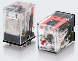
- Rơ le trung gian OMRON MY-GS
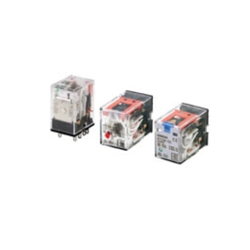
Rơ le trung gian OMRON MY-GS
Giá bán :
Liên hệ
Số lượng :
Tình trạng :
Còn hàng
-
Mã SP3965
-
Thương hiệu
-
Xuất xứJAPAN
-
Bảo hành12 THÁNG
Mô tả ngắn:
Rơ le trung gian OMRON MY-GS được chế tạo với độ chính xác và độ bền cao, điều này đã được chứng minh bởi sự tin cậy và tín nhiệm của người dùng trong hơn nửa thập kỉ qua.
BẠN CẦN HỖ TRỢ?

Mô tả sản phẩm
Rơ le trung gian OMRON dòng MY-GS
Công ty TNHH Ngân Anh Phát chuyên cung cấp dòng sản phẩm Rơ le trung gian OMRON MY-GS chính hãng xuất xứ Japan tại thị trường Việt Nam.
Đặc điểm nổi bật của rơ le trung gian OMRON MY-GS series
• Một loạt các model có thêm cần gạt để kiểm tra mạch dễ dàng hơn.
• Giảm 60% công việc đi dây khi kết hợp với Ổ cắm PYF-PU Push-In Plus (theo các phép đo thực tế).
• Rơ le với cuộn dây AC và DC có màu sắc khác nhau của chỉ báo hoạt động (đèn LED).
• Thông số kỹ thuật được in trên băng cuộn.
• Các chỉ số hoạt động cơ học là một tính năng tiêu chuẩn trên tất cả các model.
• Tiêu chuẩn UL, CSA, IEC (chứng nhận VDE), RoHS và CQC.
Thông số kỹ thuật
Thông số kỹ thuật
Operating Coil
| Item | Rated current (mA) |
Coil resis- tance (Ω) |
Coil inductance (H) |
Must- operate voltage |
Must- release voltage |
Maxi- mum voltage |
Power consumption (VA, W) |
|||
|---|---|---|---|---|---|---|---|---|---|---|
| Rated voltage | 50 Hz | 60 Hz | Armature OFF |
Armature ON |
Percentage of rated voltage | |||||
| AC | 12 | 106.5 | 91 | 46 | 0.17 | 0.33 | 80% max. *1 |
30% min. *2 |
110% | Approx. 0.9 to 1.3 (at 60 Hz) |
| 24 | 53.8 | 46 | 180 | 0.69 | 1.3 | |||||
| 48 | 25.7 | 21.1 | 788 | 3.22 | 5.66 | |||||
| 100/110 | 11.7/12.9 | 10.0/11.0 | 3,750 | 14.54 | 24.6 | |||||
| 110/120 | 9.9/10.8 | 8.4/9.2 | 4,430 | 19.2 | 32.1 | |||||
| 200/220 | 6.2/6.8 | 5.3/5.8 | 12,950 | 54.75 | 94.07 | |||||
| 220/240 | 5.2/6.2 | 4.3/5.0 | 15,920 | 83.5 | 136.4 | |||||
| DC | 6 | 146 (151) | 41.0 (39.8) |
0.17 | 0.33 | 10% min. *2 |
Approx. 0.9 | |||
| 12 | 72.7 (75) | 165 (160) |
0.73 | 1.37 | ||||||
| 24 | 36.3 (37.7) | 662 (636) |
3.2 | 5.72 | ||||||
| 48 | 17.6 (18.8) | 2,725 (2,560) |
10.6 | 21.0 | ||||||
| 100/110 | 8.7 (9.0)/9.6 (9.9) | 11,440 (11,100) |
45.6 | 86.2 | ||||||
| 220 | 3.6 | 60,394 | 362.3 | 452.9 | Approx. 0.8 | |||||
Contacts
| 2 poles | 4 poles | |||||
|---|---|---|---|---|---|---|
| Resistive load | Inductive load (cos φ = 0.4, L/R = 7 ms) |
Resistive load | Inductive load (cos φ = 0.4, L/R = 7 ms) |
|||
| Contact configuration | DPDT | 4PDT | ||||
| Contact structure | Single | |||||
| Contact material | Ag | |||||
| Rated load | 10 A at 250 VAC 10 A at 30 VDC |
5 A at 220 VDC 5 A at 24 VDC |
2 A at 220 VAC 2 A at 24 VDC |
6 A at 250 VDC 6 A at 30 VDC |
3 A at 220 VDC 3 A at 24 VDC |
0.8 A at 220 VAC 1.5 A at 24 VDC |
| Electrical endurance *1 | 100,000 operations |
500,000 operations | 30,000 operations |
200,000 operations | ||
| Rated carry current *2 | 10 A | 6 A *2 | ||||
| Maximum contact voltage | 250 VAC, 220 VDC | 250 VAC, 220 VDC | ||||
| Maximum contact current *2 | 10 A | 6 A *2 | ||||
| Maximum switching capacity | 2,500 VA 300 W |
440 VA 48 W |
1,500 VA 180 W |
176 VA 36 W |
||
| Minimum load (reference values) *3 |
1 mA at 5 VDC | |||||
Characteristics
Main unit
| 2 poles | 4 poles | ||
|---|---|---|---|
| Contact resistance *1 | 100 mΩ max. | ||
| Operation time *2 | 20 ms max. | ||
| Release time *2 | 20 ms max. | ||
| Maximum operating frequency |
Mechanical | 18, 000 operations/h | |
| Rated load | 2,400 operations/h | ||
| Insulation resistance *3 | 1,000 MΩ min. | ||
| Dielectric strength |
Between coil and contacts |
2,000 VAC at 50/60 Hz for 1 min. | |
| Between contacts of different polarity |
2,000 VAC at 50/60 Hz for 1 min. | ||
| Between contacts of the same polarity |
1,000 VAC at 50/60 Hz for 1 min. | ||
| Vibration resistance |
Destruction | 10 to 55 to 10 Hz, Double amplitude: 1.0 mm | |
| Malfunction | 10 to 55 to 10 Hz, Double amplitude: 1.0 mm | ||
| Shock resistance |
Destruction | 1,000 m/s2 (approx. 100 G) | |
| Malfunction | 200 m/s2 (Approx. 20 G) | ||
| Mechanical endurance | 50,000,000 operations (switching frequency: 18,000 operations/h) | ||
| Ambient operating temperature | Standard models: -55 to 70°C (with no icing or condensation) Models with LED operation indicators: -40 to 70°C (with no icing or condensation) |
||
| Ambient humidity | 5% to 85% | ||
| Weight | Approx. 35 g | ||
Options (order separately)
Sockets
| Model | Con- nec- tion |
Num- ber of Pins |
Ter- minal Type |
Ambi- ent operat- ing tem- pera- ture |
Am- bient hu- midity |
Con- tinuous carry current |
Dielectric strength | Insu- lation re- sistance *1 |
Weight | ||
|---|---|---|---|---|---|---|---|---|---|---|---|
| Between contact termi- nals of same polarity |
Between contact termi- nals of different polarity |
Between coil and contact termi- nals |
|||||||||
| PYFZ-08-E | Front | 8 | Screw termi- nal |
-55 to 70°C |
5% to 85% RH |
10 A | 2,250 VAC 1 min |
2,250 VAC 1 min |
2,250 VAC 1 min |
1,000 MΩ min. (500 VDC) |
Approx. 32 g |
| PYF08A-N | -55 to 55°C |
5% to 85% RH |
7A *3 | 2,000 VAC 1 min |
2,000 VAC 1 min |
2,000 VAC 1 min |
1,000 MΩ min. (500 VDC) |
Approx. 32 g |
|||
| PYF-08-PU | Push- In Plus Termi- nal |
-40 to 70°C |
5% to 85% RH |
10A *2 | 2,000 VAC 1 min |
2,000 VAC 1 min |
2,000 VAC 1 min |
1,000 MΩ min. (500 VDC) |
Approx. 80 g |
||
| PYFZ-14-E | 14 | Screw termi- nal |
-55 to 70°C |
5% to 85% RH |
6A | 2,250 VAC 1 min |
2,250 VAC 1 min |
2,250 VAC 1 min |
1,000 MΩ min. (500 VDC) |
Approx. 50 g |
|
| PYF14A-N | -55 to 55°C |
5% to 85% RH |
5A *3 | 2,000 VAC 1 min |
2,000 VAC 1 min |
2,000 VAC 1 min |
1,000 MΩ min. (500 VDC) |
Approx. 50 g |
|||
| PYF-14-PU | Push- In Plus Termi- nal |
-40 to 70°C |
5% to 85% RH |
6A | 2,000 VAC 1 min |
2,000 VAC 1 min |
2,000 VAC 1 min |
1,000 MΩ min. (500 VDC) |
Approx. 87 g |
||
| PY08-02 | Back | 8 | PCB termi- nals |
-55 to 70°C |
5% to 85% RH |
7A | 1,500 VAC 1 min |
1,500 VAC 1 min |
1,500 VAC 1 min |
100 MΩ min. |
Approx. 7.2 g |
| PY14-02 | 14 | -55 to 70°C |
5% to 85% RH |
3A | 1,500 VAC 1 min |
1,500 VAC 1 min |
1,500 VAC 1 min |
100 MΩ min. |
Approx. 10 g |
||
SẢN PHẨM LIÊN QUAN


Nhận xét sản phẩm
VỀ CHÚNG TÔI
HỖ TRỢ KHÁCH HÀNG
like facebook
CÔNG TY TNHH NGÂN ANH PHÁT
- Đ3, Đường Đồng Khởi, Tổ 23, Khu phố 35, Phường Tam Hiệp, Tỉnh Đồng Nai, Việt Nam
- (+84) 2513 857 563
- info@ngananhphat.com, sales@ngananhphat.com
- www.ngananhphat.com
Copyright © CÔNG TY TNHH NGÂN ANH PHÁT

Giấy phép đăng ký kinh doanh số : 3600955737 do Sở Kế Hoạch & Đầu Tư Tỉnh Đồng Nai cấp ngày 19/11/2007.