
MENU
Category
- AUTOMATION
- MACHINE DEVICE
- CONSTRUCT DEVICE
- FACTORY DEVICE
- TESTING DEVICE
- TENSION MEASUREMENT
- TRACTION MEASUREMENT
- TORQUE MEASUREMENT
- RPM MEASUREMENT
- THICKNESS MEASUREMENT
- STIFFNESS MEASUREMENT
- DISTANCE MEASUREMENT
- VISCOSITY MEASUREMENT
- FLOW/LEVEL MEASUREMENT
- DEPTH MEASUREMENT
- DIAL INDICATOR
- MICROMETER
- CALIPER
- MEASUREMENT ACCESSORIES
- MICROSCOPE
- MAGNIFIER
- TENSION TESTOR
- LINEAR SCALE
- TEMPERATURE MEASUREMENT
- WIND MEASUREMENT
- SOUND MEASUREMENT
- SPEED MEASUREMENT
- DENSITY MEASUREMENT
- CURRENT MEASUREMENT
- WEIGHT MEASUREMENT
- CALIPERS
- ENVICONMENT DEVICE
- SOLAR PRODUCTS
-
 AUTOMATION
CategoryBrand
AUTOMATION
CategoryBrand


-
 MACHINE DEVICE
-
 CONSTRUCT DEVICE
-
 FACTORY DEVICE
-
 TESTING DEVICE
Category
TESTING DEVICE
Category- TENSION MEASUREMENT
- TRACTION MEASUREMENT
- TORQUE MEASUREMENT
- RPM MEASUREMENT
- THICKNESS MEASUREMENT
- STIFFNESS MEASUREMENT
- DISTANCE MEASUREMENT
- VISCOSITY MEASUREMENT
- FLOW/LEVEL MEASUREMENT
- DEPTH MEASUREMENT
- DIAL INDICATOR
- MICROMETER
- CALIPER
- MEASUREMENT ACCESSORIES
- MICROSCOPE
- MAGNIFIER
- LINEAR SCALE
- TEMPERATURE MEASUREMENT
- WIND MEASUREMENT
- SOUND MEASUREMENT
- SPEED MEASUREMENT
- DENSITY MEASUREMENT
- CURRENT MEASUREMENT
- WEIGHT MEASUREMENT
Brand


-
 ENVICONMENT DEVICE
Brand
ENVICONMENT DEVICE
Brand


- Home Page
- Product
- AUTOMATION
- RELAY
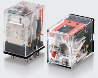
- MY-GS Miniature Power Relays OMRON
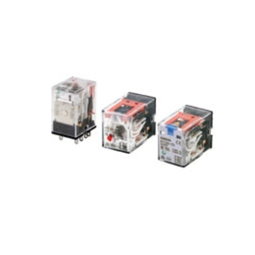
MY-GS Miniature Power Relays OMRON
Price :
Contact
Quantity :
Status :
In Stock
-
Product No3965
-
Brand
-
OriginJAPAN
-
Guarantee12 MONTHS
Mô tả ngắn:
Mechanical Indicators Added as a Standard Feature to Our Best-selling MY General-purpose Relays
DO YOU NEED SUPPORT ?

Product Description
MY-GS Miniature Power Relays OMRON
Ngan Anh Phat Co., Ltd specializes in providing genuine products MY-GS Miniature Power Relays from the manufacturer Omron, originating from Japan, to the Vietnamese market.
Outstanding features of the OMRON MY-GS series relay:
- A range of models with an additional lever for easier circuit testing.
- Reduces wiring work by 60% when combined with the PYF-PU Push-In Plus so
- Relays with AC and DC coils have different colors for the operat
- Specifications are printed on t
- Mechanical operating indicators are a standard featu
- Certified to UL, CSA, IEC (VDE certification), RoHS, and CQC standards.
Specifications
Specifications
Operating Coil
| Item | Rated current (mA) |
Coil resis- tance (Ω) |
Coil inductance (H) |
Must- operate voltage |
Must- release voltage |
Maxi- mum voltage |
Power consumption (VA, W) |
|||
|---|---|---|---|---|---|---|---|---|---|---|
| Rated voltage | 50 Hz | 60 Hz | Armature OFF |
Armature ON |
Percentage of rated voltage | |||||
| AC | 12 | 106.5 | 91 | 46 | 0.17 | 0.33 | 80% max. *1 |
30% min. *2 |
110% | Approx. 0.9 to 1.3 (at 60 Hz) |
| 24 | 53.8 | 46 | 180 | 0.69 | 1.3 | |||||
| 48 | 25.7 | 21.1 | 788 | 3.22 | 5.66 | |||||
| 100/110 | 11.7/12.9 | 10.0/11.0 | 3,750 | 14.54 | 24.6 | |||||
| 110/120 | 9.9/10.8 | 8.4/9.2 | 4,430 | 19.2 | 32.1 | |||||
| 200/220 | 6.2/6.8 | 5.3/5.8 | 12,950 | 54.75 | 94.07 | |||||
| 220/240 | 5.2/6.2 | 4.3/5.0 | 15,920 | 83.5 | 136.4 | |||||
| DC | 6 | 146 (151) | 41.0 (39.8) |
0.17 | 0.33 | 10% min. *2 |
Approx. 0.9 | |||
| 12 | 72.7 (75) | 165 (160) |
0.73 | 1.37 | ||||||
| 24 | 36.3 (37.7) | 662 (636) |
3.2 | 5.72 | ||||||
| 48 | 17.6 (18.8) | 2,725 (2,560) |
10.6 | 21.0 | ||||||
| 100/110 | 8.7 (9.0)/9.6 (9.9) | 11,440 (11,100) |
45.6 | 86.2 | ||||||
| 220 | 3.6 | 60,394 | 362.3 | 452.9 | Approx. 0.8 | |||||
Contacts
| 2 poles | 4 poles | |||||
|---|---|---|---|---|---|---|
| Resistive load | Inductive load (cos φ = 0.4, L/R = 7 ms) |
Resistive load | Inductive load (cos φ = 0.4, L/R = 7 ms) |
|||
| Contact configuration | DPDT | 4PDT | ||||
| Contact structure | Single | |||||
| Contact material | Ag | |||||
| Rated load | 10 A at 250 VAC 10 A at 30 VDC |
5 A at 220 VDC 5 A at 24 VDC |
2 A at 220 VAC 2 A at 24 VDC |
6 A at 250 VDC 6 A at 30 VDC |
3 A at 220 VDC 3 A at 24 VDC |
0.8 A at 220 VAC 1.5 A at 24 VDC |
| Electrical endurance *1 | 100,000 operations |
500,000 operations | 30,000 operations |
200,000 operations | ||
| Rated carry current *2 | 10 A | 6 A *2 | ||||
| Maximum contact voltage | 250 VAC, 220 VDC | 250 VAC, 220 VDC | ||||
| Maximum contact current *2 | 10 A | 6 A *2 | ||||
| Maximum switching capacity | 2,500 VA 300 W |
440 VA 48 W |
1,500 VA 180 W |
176 VA 36 W |
||
| Minimum load (reference values) *3 |
1 mA at 5 VDC | |||||
Characteristics
Main unit
| 2 poles | 4 poles | ||
|---|---|---|---|
| Contact resistance *1 | 100 mΩ max. | ||
| Operation time *2 | 20 ms max. | ||
| Release time *2 | 20 ms max. | ||
| Maximum operating frequency |
Mechanical | 18, 000 operations/h | |
| Rated load | 2,400 operations/h | ||
| Insulation resistance *3 | 1,000 MΩ min. | ||
| Dielectric strength |
Between coil and contacts |
2,000 VAC at 50/60 Hz for 1 min. | |
| Between contacts of different polarity |
2,000 VAC at 50/60 Hz for 1 min. | ||
| Between contacts of the same polarity |
1,000 VAC at 50/60 Hz for 1 min. | ||
| Vibration resistance |
Destruction | 10 to 55 to 10 Hz, Double amplitude: 1.0 mm | |
| Malfunction | 10 to 55 to 10 Hz, Double amplitude: 1.0 mm | ||
| Shock resistance |
Destruction | 1,000 m/s2 (approx. 100 G) | |
| Malfunction | 200 m/s2 (Approx. 20 G) | ||
| Mechanical endurance | 50,000,000 operations (switching frequency: 18,000 operations/h) | ||
| Ambient operating temperature | Standard models: -55 to 70°C (with no icing or condensation) Models with LED operation indicators: -40 to 70°C (with no icing or condensation) |
||
| Ambient humidity | 5% to 85% | ||
| Weight | Approx. 35 g | ||
Options (order separately)
Sockets
| Model | Con- nec- tion |
Num- ber of Pins |
Ter- minal Type |
Ambi- ent operat- ing tem- pera- ture |
Am- bient hu- midity |
Con- tinuous carry current |
Dielectric strength | Insu- lation re- sistance *1 |
Weight | ||
|---|---|---|---|---|---|---|---|---|---|---|---|
| Between contact termi- nals of same polarity |
Between contact termi- nals of different polarity |
Between coil and contact termi- nals |
|||||||||
| PYFZ-08-E | Front | 8 | Screw termi- nal |
-55 to 70°C |
5% to 85% RH |
10 A | 2,250 VAC 1 min |
2,250 VAC 1 min |
2,250 VAC 1 min |
1,000 MΩ min. (500 VDC) |
Approx. 32 g |
| PYF08A-N | -55 to 55°C |
5% to 85% RH |
7A *3 | 2,000 VAC 1 min |
2,000 VAC 1 min |
2,000 VAC 1 min |
1,000 MΩ min. (500 VDC) |
Approx. 32 g |
|||
| PYF-08-PU | Push- In Plus Termi- nal |
-40 to 70°C |
5% to 85% RH |
10A *2 | 2,000 VAC 1 min |
2,000 VAC 1 min |
2,000 VAC 1 min |
1,000 MΩ min. (500 VDC) |
Approx. 80 g |
||
| PYFZ-14-E | 14 | Screw termi- nal |
-55 to 70°C |
5% to 85% RH |
6A | 2,250 VAC 1 min |
2,250 VAC 1 min |
2,250 VAC 1 min |
1,000 MΩ min. (500 VDC) |
Approx. 50 g |
|
| PYF14A-N | -55 to 55°C |
5% to 85% RH |
5A *3 | 2,000 VAC 1 min |
2,000 VAC 1 min |
2,000 VAC 1 min |
1,000 MΩ min. (500 VDC) |
Approx. 50 g |
|||
| PYF-14-PU | Push- In Plus Termi- nal |
-40 to 70°C |
5% to 85% RH |
6A | 2,000 VAC 1 min |
2,000 VAC 1 min |
2,000 VAC 1 min |
1,000 MΩ min. (500 VDC) |
Approx. 87 g |
||
| PY08-02 | Back | 8 | PCB termi- nals |
-55 to 70°C |
5% to 85% RH |
7A | 1,500 VAC 1 min |
1,500 VAC 1 min |
1,500 VAC 1 min |
100 MΩ min. |
Approx. 7.2 g |
| PY14-02 | 14 | -55 to 70°C |
5% to 85% RH |
3A | 1,500 VAC 1 min |
1,500 VAC 1 min |
1,500 VAC 1 min |
100 MΩ min. |
Approx. 10 g |
||


Product Reviews
ABOUT NGAN ANH PHAT
CUSTOMER SUPPORT
CUSTOMER SERVICES
like facebook
NGAN ANH PHAT CO.,LTD
- D3, Dong Khoi, Group 23, Quarter 35, Tam Hiep Ward, Dong Nai Province, Vietnam
- (+84) 2513 857 563
- info@ngananhphat.com, sales@ngananhphat.com
- www.ngananhphat.com
Copyright © CÔNG TY TNHH NGÂN ANH PHÁT

Giấy phép đăng ký kinh doanh số : 3600955737 do Sở Kế Hoạch & Đầu Tư Tỉnh Đồng Nai cấp ngày 19/11/2007.