
- TỰ ĐỘNG HÓA
- THIẾT BỊ CƠ KHÍ
- CÔNG DỤNG CỤ
- THIẾT BỊ KHO XƯỞNG
- THIẾT BỊ ĐO
- ĐO LỰC CĂNG
- ĐO LỰC KÉO
- ĐO MÔ MEN XOẮN
- ĐO TỐC ĐỘ VÒNG QUAY
- ĐO ĐỘ DÀY
- ĐO ĐỘ CỨNG
- ĐO KHOẢNG CÁCH
- ĐO ĐỘ NHỚT
- ĐO MỨC CHẤT LỎNG
- ĐO ĐỘ SÂU
- ĐỒNG HỒ SO
- THƯỚC PANME
- THƯỚC ĐO
- PHỤ KIỆN ĐO
- KÍNH HIỂN VI
- KÍNH LÚP
- THƯỚC QUANG
- ĐO NHIỆT ĐỘ
- ĐO SỨC GIÓ
- ĐO ÂM THANH
- ĐO TỐC ĐỘ
- ĐO MẬT ĐỘ
- ĐO DÒNG ĐIỆN
- ĐO KHỐI LƯỢNG
- THƯỚC KẸP
- THIẾT BỊ MÔI TRƯỜNG
- GIA CÔNG CƠ KHÍ
-
 TỰ ĐỘNG HÓA
Danh mụcThương hiệu
TỰ ĐỘNG HÓA
Danh mụcThương hiệu


-
 THIẾT BỊ CƠ KHÍ
-
 CÔNG DỤNG CỤ
-
 THIẾT BỊ KHO XƯỞNG
-
 THIẾT BỊ ĐO
Danh mụcThương hiệu
THIẾT BỊ ĐO
Danh mụcThương hiệu


-
 THIẾT BỊ MÔI TRƯỜNG
Danh mụcThương hiệu
THIẾT BỊ MÔI TRƯỜNG
Danh mụcThương hiệu


- Trang chủ
- Sản phẩm
- TỰ ĐỘNG HÓA
- RELAY
- Rơ le bán dẫn OMRON G9H
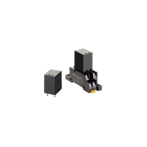
Rơ le bán dẫn OMRON G9H
-
Mã SP4028
-
Thương hiệu
-
Xuất xứJAPAN
-
Bảo hành12 THÁNG

Rơ le bán dẫn OMRON G9H
Công ty TNHH Ngân Anh Phát chuyên cung cấp dòng sản phẩm Rơ le bán dẫn OMRON G9H chính hãng xuất xứ Japan tại thị trường Việt Nam.
Đặc điểm nổi bật của Rơ le bán dẫn OMRON G9H :
• Giảm công việc đi dây đến 60% khi kết hợp với ổ cắm Push-In Plus PTF-08-PU (theo các phép đo thực tế của OMRON).
• Chứng nhận UL/CSA (-US models).
• Sử dụng triac để đóng và mở mạch giúp giảm hiện tượng kêu và hồ quang, từ đó tăng độ bền điện lên đến 10 triệu lần hoạt động.
• Các tiếp điểm rơ le cho việc bật nguồn và chuyển mạch 10 A với công suất lớn được cung cấp trong một thân máy nhỏ gọn mà không cần bộ tản nhiệt. Hơn nữa, gần như không có ảnh hưởng đến nhiệt độ phát sinh hoặc nhiệt độ môi trường.
• Đèn báo hoạt động giúp dễ dàng kiểm tra trạng thái hoạt động.
• Cầu chì nhiệt tích hợp ngăn ngừa tình trạng cháy nội bộ do sự cố của triac hoặc rơ le.
• Rơ le loại ổ cắm có cùng kích thước với rơ le 1 cực và 2 cực LY.
Thông số kỹ thuật
Ratings
Input
| Rated voltage |
Item | Operating voltage | Coil resistance |
Must operate voltage |
Must release voltage |
Power consumption |
|---|---|---|---|---|---|---|
| DC | 5 V | 4 to 6 VDC | 104 Ω | 4 VDC max. | 0.5 VDC min. | Approx. 240 mW |
| 12 V | 9.6 to 14.4 VDC | 600 Ω | 9.6 VDC max. | 1.2 VDC min. | ||
| 24 V | 19.2 to 28. 8 VDC | 2,400 Ω | 19.2 VDC max. | 2.4 VDC min. |
Note: 1. The coil resistance is measured at a coil temperature of 23°C with a tolerance of ±10%.
2. Performance characteristic data are measured at a coil temperature of 23°C.
Output
| Item | Applicable load | |||
|---|---|---|---|---|
| Model | Rated load voltage |
Load voltage range |
Load current (See note.) |
Inrush current resistance |
| G9H-205S-US | 100 to 240 VAC | 75 to 264 VAC | 50 mA to 5 A (at 55°C) | 80 A (60 Hz, 1 cycle) |
| G9H-210S-US | 50 mA to 10 A (at 55°C) | 170 A (60 Hz, 1 cycle) | ||
Note: The load current depends on the ambient temperature. For details, refer to Load Current vs. Ambient Temperature
in Engineering Data.
Characteristics
| Item | G9H-205S-US | G9H-210S-US | |
|---|---|---|---|
| Operate time | 10 ms max. | ||
| Release time | 1/2 cycle max. + 10 ms | ||
| Output ON voltage drop | 1.6 V max. (RMS) (at 5 A) | 1.6 V max. (RMS) (at 10 A) | |
| Leakage current | 5 mA max. at 250 VAC | ||
| Inrush current resistance | 80 A | 170 A | |
| Temperature rise | 50°C max. (rated voltage applied using resistance method) | ||
| Insulation resistance | 100 MΩ min. (at 500 VDC) | ||
| Dielectric strength | 2,000 VAC 50/60 Hz 1 min | ||
| Vibration resistance |
Destruction | 10 to 55 to 10 Hz, 1-mm single amplitude (2-mm double amplitude) | |
| Malfunction | 10 to 45 to 10 Hz, 1-mm single amplitude (2-mm double amplitude) | ||
| Shock resistance (See note.) |
Destruction | 1,000 m/s2 | |
| Malfunction | 100 m/s2 | ||
| Life expectancy | Mechanical | 10 million operations min. (switching frequency: 18,000 operations/hour) | |
| Electrical | 10 million operations min. (resistive load and switching frequency: 18,000 operations/hour) | ||
| Storage temperature | -25 to 70°C (with no icing or condensation) | ||
| Ambient operating temperature | -25 to 60°C (with no icing or condensation) | ||
| Ambient operating humidity | 35% to 85% | ||
| Weight | Approx. 25 g | ||
Note: Value when excited.
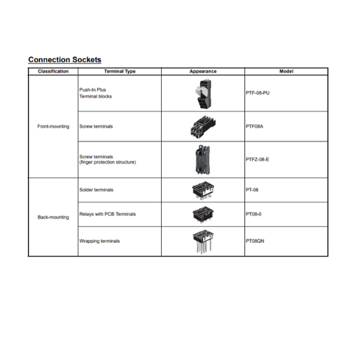
Accessories (Order Separately)
Socket Characteristics
| Model | Rated carry current |
Dielectric strength | Insulation resistance *1 |
Remarks |
|---|---|---|---|---|
| PTF-08-PU | 10 A | Between contact terminals of different polarity: 2,000 VAC, 1 min | 1,000 MΩ min. | |
| Between contact terminals of same polarity: 2,000 VAC, 1 min | ||||
| Between coil and contact terminals: 2,000 VAC, 1 min | ||||
| PTFZ-08-E | 12 A (@70°C) *2 |
Between contact terminals of different polarity: 2,500 VAC, 1 min | 1,000 MΩ min. | |
| Between contact terminals of same polarity: 2,500 VAC, 1 min | ||||
| Between ground terminals: 2,500 VAC, 1 min | ||||
| Between coil and contact terminals: 2,500 VAC, 1 min | ||||
| PTF08A | 10 A | Between terminals: 2,000 VAC for 1 min | 100 MΩ min. | |
| PT-08 | 10 A | Between terminals: 2,000 VAC for 1 min | 100 MΩ min. | |
| PT08-0 | 10 A | Between terminals: 2,000 VAC for 1 min | 100 MΩ min. | |
| PT08QN | 10 A | Between terminals: 2,000 VAC for 1 min | 100 MΩ min. |
*1 The insulation resistance was measured with a 500-VDC insulation resistance meter at the same places as those used for measuring the dielectric strength.
*2 However, do not exceed the continuous carry current of the socket to be mounted.
SẢN PHẨM LIÊN QUAN


- Đ3, Đường Đồng Khởi, Tổ 23, Khu phố 35, Phường Tam Hiệp, Tỉnh Đồng Nai, Việt Nam
- (+84) 2513 857 563
- info@ngananhphat.com, sales@ngananhphat.com
- www.ngananhphat.com

Giấy phép đăng ký kinh doanh số : 3600955737 do Sở Kế Hoạch & Đầu Tư Tỉnh Đồng Nai cấp ngày 19/11/2007.