
- AUTOMATION
- MACHINE DEVICE
- CONSTRUCT DEVICE
- FACTORY DEVICE
- TESTING DEVICE
- TENSION MEASUREMENT
- TRACTION MEASUREMENT
- TORQUE MEASUREMENT
- RPM MEASUREMENT
- THICKNESS MEASUREMENT
- STIFFNESS MEASUREMENT
- DISTANCE MEASUREMENT
- VISCOSITY MEASUREMENT
- FLOW/LEVEL MEASUREMENT
- DEPTH MEASUREMENT
- DIAL INDICATOR
- MICROMETER
- CALIPER
- MEASUREMENT ACCESSORIES
- MICROSCOPE
- MAGNIFIER
- TENSION TESTOR
- LINEAR SCALE
- TEMPERATURE MEASUREMENT
- WIND MEASUREMENT
- SOUND MEASUREMENT
- SPEED MEASUREMENT
- DENSITY MEASUREMENT
- CURRENT MEASUREMENT
- WEIGHT MEASUREMENT
- CALIPERS
- ENVICONMENT DEVICE
- SOLAR PRODUCTS
-
 AUTOMATION
CategoryBrand
AUTOMATION
CategoryBrand


-
 MACHINE DEVICE
-
 CONSTRUCT DEVICE
-
 FACTORY DEVICE
-
 TESTING DEVICE
Category
TESTING DEVICE
Category- TENSION MEASUREMENT
- TRACTION MEASUREMENT
- TORQUE MEASUREMENT
- RPM MEASUREMENT
- THICKNESS MEASUREMENT
- STIFFNESS MEASUREMENT
- DISTANCE MEASUREMENT
- VISCOSITY MEASUREMENT
- FLOW/LEVEL MEASUREMENT
- DEPTH MEASUREMENT
- DIAL INDICATOR
- MICROMETER
- CALIPER
- MEASUREMENT ACCESSORIES
- MICROSCOPE
- MAGNIFIER
- LINEAR SCALE
- TEMPERATURE MEASUREMENT
- WIND MEASUREMENT
- SOUND MEASUREMENT
- SPEED MEASUREMENT
- DENSITY MEASUREMENT
- CURRENT MEASUREMENT
- WEIGHT MEASUREMENT
Brand


-
 ENVICONMENT DEVICE
Brand
ENVICONMENT DEVICE
Brand


- Home Page
- Product
- AUTOMATION
- RELAY
- Hybrid Power Relay G9H OMRON
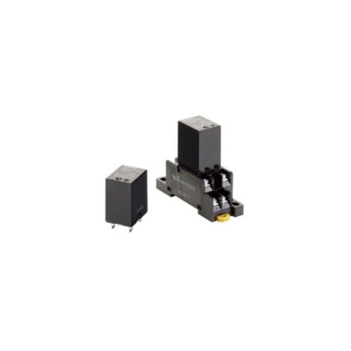
Hybrid Power Relay G9H OMRON
-
Product No4028
-
Brand
-
OriginJAPAN
-
Guarantee12 MONTHS
Hybridization of a Magnetic Relay and an SSR Achieves 10-A Switching for 10 Million Operations.

Hybrid Power Relay G9H OMRON
Ngan Anh Phat Co., Ltd specializes in providing genuine products Hybrid Power Relay G9H OMRON from the manufacturer Omron, originating from Japan, to the Vietnamese market.
Outstanding features of the Hybrid Power Relay G9H OMRON:
• Reduces wiring work by 60% when combined with the PTF-08-PU Push-In Plus Socket (according to actual OMRON measurements).
• UL/CSA certified (-US models).
• Using a triac to open and close the circuit reduces chattering and arching, thereby increasing the electrical durability to 10 million operations.
• Relays contacts for power ON and 10-A switching with high-capacity are provided in a compact body without the need of radiators. Plus, there is almost no effect on heat generation or ambient temperature.
• Operation indicators to easily check operation.
• Built-in temperature fuse prevents internal burning due to triac or relay malfunctions.
• Socket-type Relays the same size as the 1-pole and 2-pole LY Relays.
Specifications
Ratings
Input
| Rated voltage |
Item | Operating voltage | Coil resistance |
Must operate voltage |
Must release voltage |
Power consumption |
|---|---|---|---|---|---|---|
| DC | 5 V | 4 to 6 VDC | 104 Ω | 4 VDC max. | 0.5 VDC min. | Approx. 240 mW |
| 12 V | 9.6 to 14.4 VDC | 600 Ω | 9.6 VDC max. | 1.2 VDC min. | ||
| 24 V | 19.2 to 28. 8 VDC | 2,400 Ω | 19.2 VDC max. | 2.4 VDC min. |
Note: 1. The coil resistance is measured at a coil temperature of 23°C with a tolerance of ±10%.
2. Performance characteristic data are measured at a coil temperature of 23°C.
Output
| Item | Applicable load | |||
|---|---|---|---|---|
| Model | Rated load voltage |
Load voltage range |
Load current (See note.) |
Inrush current resistance |
| G9H-205S-US | 100 to 240 VAC | 75 to 264 VAC | 50 mA to 5 A (at 55°C) | 80 A (60 Hz, 1 cycle) |
| G9H-210S-US | 50 mA to 10 A (at 55°C) | 170 A (60 Hz, 1 cycle) | ||
Note: The load current depends on the ambient temperature. For details, refer to Load Current vs. Ambient Temperature
in Engineering Data.
Characteristics
| Item | G9H-205S-US | G9H-210S-US | |
|---|---|---|---|
| Operate time | 10 ms max. | ||
| Release time | 1/2 cycle max. + 10 ms | ||
| Output ON voltage drop | 1.6 V max. (RMS) (at 5 A) | 1.6 V max. (RMS) (at 10 A) | |
| Leakage current | 5 mA max. at 250 VAC | ||
| Inrush current resistance | 80 A | 170 A | |
| Temperature rise | 50°C max. (rated voltage applied using resistance method) | ||
| Insulation resistance | 100 MΩ min. (at 500 VDC) | ||
| Dielectric strength | 2,000 VAC 50/60 Hz 1 min | ||
| Vibration resistance |
Destruction | 10 to 55 to 10 Hz, 1-mm single amplitude (2-mm double amplitude) | |
| Malfunction | 10 to 45 to 10 Hz, 1-mm single amplitude (2-mm double amplitude) | ||
| Shock resistance (See note.) |
Destruction | 1,000 m/s2 | |
| Malfunction | 100 m/s2 | ||
| Life expectancy | Mechanical | 10 million operations min. (switching frequency: 18,000 operations/hour) | |
| Electrical | 10 million operations min. (resistive load and switching frequency: 18,000 operations/hour) | ||
| Storage temperature | -25 to 70°C (with no icing or condensation) | ||
| Ambient operating temperature | -25 to 60°C (with no icing or condensation) | ||
| Ambient operating humidity | 35% to 85% | ||
| Weight | Approx. 25 g | ||
Note: Value when excited.
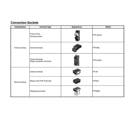
Accessories (Order Separately)
Socket Characteristics
| Model | Rated carry current |
Dielectric strength | Insulation resistance *1 |
Remarks |
|---|---|---|---|---|
| PTF-08-PU | 10 A | Between contact terminals of different polarity: 2,000 VAC, 1 min | 1,000 MΩ min. | |
| Between contact terminals of same polarity: 2,000 VAC, 1 min | ||||
| Between coil and contact terminals: 2,000 VAC, 1 min | ||||
| PTFZ-08-E | 12 A (@70°C) *2 |
Between contact terminals of different polarity: 2,500 VAC, 1 min | 1,000 MΩ min. | |
| Between contact terminals of same polarity: 2,500 VAC, 1 min | ||||
| Between ground terminals: 2,500 VAC, 1 min | ||||
| Between coil and contact terminals: 2,500 VAC, 1 min | ||||
| PTF08A | 10 A | Between terminals: 2,000 VAC for 1 min | 100 MΩ min. | |
| PT-08 | 10 A | Between terminals: 2,000 VAC for 1 min | 100 MΩ min. | |
| PT08-0 | 10 A | Between terminals: 2,000 VAC for 1 min | 100 MΩ min. | |
| PT08QN | 10 A | Between terminals: 2,000 VAC for 1 min | 100 MΩ min. |
*1 The insulation resistance was measured with a 500-VDC insulation resistance meter at the same places as those used for measuring the dielectric strength.
*2 However, do not exceed the continuous carry current of the socket to be mounted.


- D3, Dong Khoi, Group 23, Quarter 35, Tam Hiep Ward, Dong Nai Province, Vietnam
- (+84) 2513 857 563
- info@ngananhphat.com, sales@ngananhphat.com
- www.ngananhphat.com

Giấy phép đăng ký kinh doanh số : 3600955737 do Sở Kế Hoạch & Đầu Tư Tỉnh Đồng Nai cấp ngày 19/11/2007.