


Bộ định thời gian OMRON H5CX
-
Mã SP4128
-
Thương hiệu
-
Xuất xứJAPAN
-
Bảo hành12 THÁNG

Bộ định thời gian OMRON H5CX
Công ty TNHH Ngân Anh Phát chuyên cung cấp dòng sản phẩm Bộ định thời gian OMRON H5CX chính hãng xuất xứ Japan tại thị trường Việt Nam.
Đặc điểm nổi bật của Bộ định thời gian OMRON H5CX:
-
Thiết kế đa chức năng: H5CX là bộ định thời gian kỹ thuật số đa chức năng, có thể sử dụng cho nhiều ứng dụng khác nhau, bao gồm cả bộ định thời gian 2 giai đoạn, giúp tối ưu hóa hiệu suất và linh hoạt trong các yêu cầu công nghiệp.
-
Dải thời gian rộng: Bộ hẹn giờ cung cấp nhiều dải thời gian linh hoạt từ mili giây đến hàng giờ, đáp ứng các yêu cầu đa dạng trong các ứng dụng tự động hóa và điều khiển.
-
Giao diện người dùng thân thiện: Với màn hình LCD rõ ràng và giao diện trực quan, việc cài đặt và lập trình thời gian trở nên dễ dàng và chính xác.
-
Chế độ điều khiển linh hoạt: H5CX hỗ trợ nhiều chế độ hoạt động như ON/OFF, Flicker và các chế độ đặc biệt khác, giúp người dùng điều chỉnh theo nhu cầu cụ thể của hệ thống.
-
Cài đặt đơn giản: Các nút điều khiển và màn hình giúp việc cài đặt và thay đổi các tham số trở nên nhanh chóng, dễ dàng và chính xác.
-
Chức năng bảo vệ: H5CX tích hợp các tính năng bảo vệ như chống quá tải và bảo vệ dòng điện, đảm bảo độ bền và ổn định cho thiết bị trong suốt quá trình vận hành.
-
Chế độ kiểm tra trình tự dễ dàng: Hỗ trợ kiểm tra trình tự dễ dàng thông qua các đầu ra tức thời, giúp người dùng giám sát và điều chỉnh quá trình hoạt động một cách chính xác.
-
Tương thích với các thiết bị khác: H5CX có khả năng tương thích với nhiều loại rơ le và bộ điều khiển công nghiệp khác, giúp dễ dàng tích hợp vào hệ thống tự động hóa.
-
Tiết kiệm năng lượng: Thiết kế tiết kiệm năng lượng giúp giảm chi phí vận hành và bảo vệ môi trường.
-
Tuân thủ các tiêu chuẩn công nghiệp: Đạt các chứng nhận quốc tế như CE, UL, và CSA, đảm bảo chất lượng và độ tin cậy cao trong các ứng dụng công nghiệp.
Thông số kỹ thuật
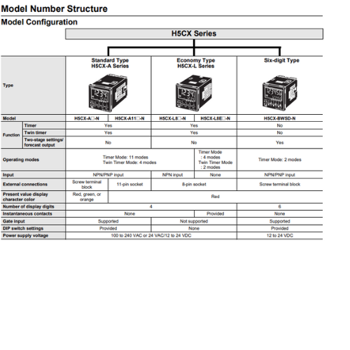
H5CX-A[]-N/-L[]-N Digital Timers
Ratings
| Models | H5CX-A[]-N | H5CX-A11[]-N | H5CX-L8[]-N | |
|---|---|---|---|---|
| Classification | Standard Type | Economy Type | ||
| Ratings | Power supply voltage *1 |
100 to 240 VAC 50/60 Hz 12 to 24 VDC/24 VAC 50/60 Hz |
||
| Operating voltage fluctuation range |
85% to 110% of rated supply voltage (90% to 110% at 12 to 24 VDC) | |||
| Power consumption | Approx. 6.2 VA at 100 to 240 VAC, Approx. 5.1 VA/2.4 W at 24 VAC/12 to 24 VDC *2 | |||
| Mounting method | Flush mounting | Flush mounting, surface mounting, DIN track mounting | ||
| External connections | Screw terminals | 11-pin socket | 8-pin socket | |
| Degree of protection | IEC IP66, UL508 Type 4X (indoors) for panel surface only and when Y92S-29 Waterproof Packing is used |
|||
| Digits | 4 digits | |||
| Time ranges | 0.001 s to 9.999 s, 0.01 s to 99.99 s, 0.1 s to 999.9 s, 1 s to 9999 s, 1 s ti 99 min 59 s 0.1 m to 999.9 min, 1 min to 9999 min, 1 min to 99 h 59 min, 0.1 h to 999.9 h, 1 h to 9999 h |
|||
| Timer mode | Elapsed time (Up), remaining time (Down) (selectable) | |||
| Inputs | Input signals | Signal, Reset, Gate | Signal, Reset (no inputs on models with instantaneous contact outputs) |
|
| Input method | No-voltage (NPN) input/ voltage (PNP) input (switchable) No-voltage Input ON impedance: 1 kΩ max. (Leakage current: 12 mA when 0 Ω) ON residual voltage: 3 V max. OFF impedance: 100 kΩ min. Voltage Input High (logic) level: 4.5 to 30 VDC Low (logic) level: 0 to 2 VDC (Input resistance: approx. 4.7 kΩ) |
No-voltage Input ON impedance: 1 kΩ max. (Leakage current: 12 mA when 0 Ω) ON residual voltage: 3 V max. OFF impedance: 100 kΩ min. |
||
| Signal, reset, gate | Minimum input signal width: 1 or 20 ms (selectable, same for all input) | |||
| Reset system | Power reset (depending on output mode), external reset, manual reset, automatic reset (depending on output mode) |
|||
| Power reset | Minimum power-opening time: 0.5 s (except for A-3, b-1, F, ton-1, and toff-1 mode) | |||
| Reset voltage | 10% max. of rated supply voltage | |||
| Sensor waiting time | 250 ms max. (Control output is turned OFF and no input is accepted during sensor waiting time.) |
|||
| Output | Output modes | A: Signal ON Delay I, A-1: Signal ON Delay II, A-2: Power ON Delay I, A-3: Power ON Delay II, b: Repeat Cycle 1, b-1: Repeat Cycle 2, d: Signal OFF Delay, E: Interval, F: Cumulative, Z: ON/OFF-duty-adjustable flicker, S: Stopwatch, toff: Flicker OFF Start 1, ton: Flicker ON Start 1, toff-1: Flicker OFF Start 2, ton-1: Flicker ON Start 2 |
 |
|
| Models with Instantaneous Contact Outputs A-2: Power ON Delay I, b: Repeat Cycle 1, E: Interval, Z: ON/OFF-duty-adjustable flicker, toff: Flicker OFF Start 1, ton: Flicker ON Start 1 |
||||
| One-shot output time |
0.01 to 99.99 s | |||
| Control output | Models with Contact Outputs 5 A at 250 VAC/30 VDC, resistive load (cos =1) Minimum applied load: 10 mA at 5 VDC (failure level: P, reference value) Contact materials: AgSnIn Transistor output: NPN open collector, 100 mA at 30 VDC max., residual voltage: 1.5 VDC max. (Approx. 1 V), Leakage current: 0.1 mA max. |
|||
| Display method *3 | 7-segment, negative transmissive LCD; Present value: 12-mm-high characters, (switchable between red, green, and orange) Set value: 6-mm-high characters, green |
7-segment, negative transmissive LCD; Present value: 12-mm-high characters, red Set value: 6-mm-high characters, green |
||
| Memory backup | EEPROM (overwrites: 100,000 times min.) that can store data for 10 years min. | |||
| Operating temperature range | -10 to 55°C (-10 to 50°C if counters are mounted side by side) (with no icing or condensation) |
|||
| Storage temperature range | -25 to 70°C (with no icing or condensation) | |||
| Operating humidity range | 25% to 85% | |||
| Case color | Black (N1.5) (Optional Front Panels are available to change the Front Panel color to light gray or white.) |
|||
| Attachments | Waterproof packing, flush mounting adapter, label for DIP switch settings |
Label for DIP switch settings |
--- | |
*1. Do not use the output from an inverter as the power supply. The ripple must be 20% maximum for DC power.
*2. Inrush current will flow for a short time when the power supply is turned ON.
Inrush Current (Reference Values)
| Voltage | Applied voltage | Inrush current (peak value) | Time |
|---|---|---|---|
| 100 to 240 VAC | 264 VAC | 5.3 A | 0.4 ms |
| 12 to 24 VDC/24 VAC | 26.4 VAC | 6.4 A | 1.4 ms |
| 26.4 VDC | 4.4 A | 1.7 ms |
*3. The display is lit only when the power is ON. Nothing is displayed when power is OFF.
Characteristics
| Accuracy of operating time and setting error (including temperature and voltage influences) |
Power-ON start: ±0.01% ±50 ms max. (See note 1.) Signal start: ±0.005%±30 ms max. (See note 1.) Signal start for transistor output model: ±0.005%±3 ms max. (See note 1 and 2.) If the set value is within the sensor waiting time at startup the control output of the H5CX will not turn ON until the sensor waiting time passes. Note: 1. The values are based on the set value. 2. The value is applied for a minimum pulse width of 1 ms. |
|
|---|---|---|
| Insulation resistance | 100 MΩ min. (at 500 VDC) between current-carrying terminal and exposed non-current-carrying metal parts, and between non-continuous contacts | |
| Dielectric strength | 2,000 VAC, 50/60 Hz for 1 min between current-carrying metal parts and non-current-carrying metal parts 2,000 VAC, 50/60 Hz for 1 min between power supply and input circuits for the models other than H5CX-[]D-N and H5CX-L8E[]-N 1,000 VAC, 50/60 Hz for 1 min between control output, power supply, and input circuits (for the models other than H5CX-L8E[]-N) for H5CX-[]SD-N 2,000 VAC, 50/60 Hz for 1 min between control output, power supply, and input circuits (for the models other than H5CX-L8E[]-N) for other models 1,000 VAC, 50/60 Hz for 1 min between non-continuous contacts |
|
| Impulse withstand voltage |
5 kV (between power terminals) for 100 to 240 VAC, 1 kV for 24 VAC/12 to 24 VDC 5 kV (between current-carrying terminal and exposed non-current-carrying metal parts) for 100 to 240 VAC 1.5 kV for 24 VAC/12 to 24 VDC |
|
| Noise immunity | ±1.5 kV (between power terminals) and ±600 V (between input terminals), square-wave noise by noise simulator (pulse width: 100 ns/ 1 μs, 1-ns rise) | |
| Static immunity | Malfunction: 8 kV Destruction: 15 kV |
|
| Vibration resistance |
Destruction | 10 to 55 Hz with 0.75-mm single amplitude each in three directions for 2 h each |
| Malfunction | 10 to 55 Hz with 0.35-mm single amplitude each in three directions for 10 min each | |
| Shock resistance |
Destruction | 300 m/s2 in three directions, three cycles |
| Malfunction | 100 m/s2 in three directions, three cycles | |
| Life expectancy |
Mechanical | 10,000,000 operations min. (under no load at 1,800 operations/h and ambient temperature of 23°C) |
| Electrical | 100,000 operations min. (5 A at 250 VAC, resistive load at 1,800 operations/h and ambient temperature of 23°C) * | |
| Weight | Approx. 115 g (Timer only) | |
* Refer to Life-test Curve.
Life-test Curve (Reference Values)
A maximum current of 0.15 A can be switched at 125 VDC (cosφ =1) and a maximum current of 0.1 A can be switched if L/R is 7 ms. In both cases, a life of 100,000 operations can be expected.
Applicable Standards
| Approved safety standards | UL508/Listing, UL508 Type 4X for indoor use (enclosure rating), CSA C22.2 No. 14 *1, conforms to EN61812-1 (Pollution degree 2/overvoltage category III) B300 PILOT DUTY 1/4 HP 120 VAC, 1/3 HP, 240 VAC, 5 A resistive load VDE0106/P100 CCC: GB/T 14048.5 Pollution degree 2, Overvoltage category III *2,*3 |
|---|---|
| EMC | (EMI) EN61812-1 Emission Enclosure: EN55011 Group 1 class A Emission AC mains: EN55011 Group 1 class A (EMS) EN61812-1 Immunity ESD: IEC61000-4-2 Immunity RF-interference: IEC61000-4-3 Immunity Burst: IEC61000-4-4 Immunity Surge: IEC61000-4-5 Immunity Conducted Disturbance: IEC61000-4-6 Immunity Voltage Dip/Interruption: IEC61000-4-11 |
*1. The following safety standards apply to models with sockets (H5CX-A11[] or H5CX-L8[]).
cUL (Listing): Applicable when an OMRON P2CF (-E) Socket is used.
cUR (Recognition): Applicable when any other socket is used.
*2. Excluding the H5CX-ASD-N/-A11SD-N/-L8SD-N.
*3. CCC certification requirements
| Rated operating voltage Ue Rated operating current Ie |
Contact Output: AC-15: Ue: 250 VAC, Ie: 3 A AC-13: Ue: 250 VAC, Ie: 5 A DC-13: Ue: 30 VDC, Ie: 0.5 A Transistor Output: DC-13: Ue: 30 VDC, Ie: 0.1 A |
|---|---|
| Rated insulation voltage | 250 V |
| Rated impulse withstand voltage (altitude: 2,000 m max.) |
4 kV (at 240 VAC) |
| Conditional short-circuit current |
1000 A |
I/O Functions
For details, refer to the timing charts on Data Sheet.
| Inputs *1 |
Start signal | Normally functions to start timing. In modes A-2 and A-3, disable timing. In mode S, starts and stops timing. |
|---|---|---|
| Reset | Resets present value. (In elapsed time mode, the present value returns to 0; in remaining time mode, the present value returns to the set value.) Count inputs are not accepted and control output turns OFF while reset input is ON. Reset indicator is lit while reset input is ON. |
|
| Gate *2 | Disables timing. (If a reset occurs while the gate input is ON, a reset will be performed.) | |
| Outputs | Control output (OUT) |
Outputs take place according to designated operating mode when timer reaches corresponding set value. |
*1. The H5CX-L8E[] does not have an input.
*2. The H5CX-L[] does not have a gate input.
Response Delay Time When Resetting (Transistor Output)
The following table shows the delay from when the reset signal is input until the output is turned OFF.
(Reference value)
| Minimum reset signal width | Output delay time |
|---|---|
| 1 ms | 0.8 to 1.2 ms |
| 20 ms | 15 to 25 ms |
Digital Timer H5CX-BWSD-N
Ratings
| Classification | Digital Timer with 6-digit display, 2-stage setting, and forecast output | |
|---|---|---|
| Ratings | Power supply voltage | 12 to 24 VDC |
| Operating voltage fluctuation range |
90% to 110% rated supply voltage | |
| Power consumption | Approx. 2.3 W *1 | |
| Mounting method | Flush mounting | |
| External connections | Screw terminals | |
| Degree of protection | IEC IP66, UL508 Type 4X (indoors) for panel front surface only and only when Y92S- 29 Waterproof Packing is used |
|
| Digits | 6 digits | |
| Time range | 0.01 s to 9999.99 s, 1 s to 99 h 59 min 59 s, 0.1 min to 99999.9 min, 0.1 h to 99999.9 h |
|
| Timer mode | Elapsed time (Up) | |
| Inputs | Input signals | Signal, reset, gate |
| Input method | No-voltage (NPN) input/voltage (PNP) input (switchable) No-voltage Input ON impedance: 1 kΩ max. (Leakage current: 12 mA when 0 Ω) ON residual voltage: 3 V max. OFF impedance: 100 kΩ min. Voltage Input High (logic) level: 4.5 to 30 VDC Low (logic) level: 0 to 2 VDC (Input resistance: approx. 4.7 kΩ) |
|
| Signal, reset, gate | Minimum input signal width: 1 or 20 ms (selectable, same for all input) | |
| Reset system | Power resets (only for A mode), external and manual reset | |
| Power reset | Minimum power-opening time: 0.5 s (except for F-1 mode) | |
| Reset voltage | 10% max. of rated supply voltage | |
| Sensor waiting time | 250 ms max. (Control output is turned OFF and no input is accepted during sensor waiting time.) |
|
| Outputs | Output modes | A, F-1 |
| Output type | Transistor output: NPN open collector, 100 mA at 30 VDC max. residual voltage: 1.5 VDC max. (Approx. 1 V) Leakage current: 0.1 mA max. |
|
| Display | 7-segment, negative transmissive LCD; Present value: 10-mm-high characters, red Set value: 6-mm-high characters, green *2 |
|
| Memory backup | EEPROM (overwrites: 100,000 times min.) that can store data for 10 years min. | |
| Operating temperature range | -10 to 55°C (-10 to 50°C if counters are mounted side by side) (with no icing or condensation) |
|
| Storage temperature range | -25 to 70°C (with no icing or condensation) | |
| Operating humidity range | 25 to 85% | |
| Case color | Black (N1.5) | |
| Attachments | Waterproof packing, flush mounting adapter, unit label | |
*1. Inrush current will flow for a short time when the power supply is turned ON.
Inrush Current (Reference Values)
| Voltage | Applied voltage | Inrush current (peak value) | Time |
|---|---|---|---|
| 12 to 24 VDC | 26.4 VDC | 4.4 A | 1.7 ms |
*2. The display is lit only when the power is ON.
Characteristics
| Accuracy of operating time and setting error (including temperature and voltage influences) |
Power-ON start: ±0.01% ±50 ms max. (See note 1.) Signal start: ±0.005%±0.03 ms max. (See note 1.) Signal start for transistor output model: ±0.005%±3 ms max. (See note 1 and 2.) If the set value is within the sensor waiting time at startup the control output of the H5CX will not turn ON until the sensor waiting time passes. Note: 1. The values are based on the set value. 2. The value is applied for a minimum pulse width of 1 ms. |
|
|---|---|---|
| Insulation resistance | 100 MΩ min. (at 500 VDC) between current-carrying terminal and exposed non-current-carrying metal parts | |
| Dielectric strength | 2,000 VAC, 50/60 Hz for 1 min between current-carrying metal parts and non-current-carrying metal parts 1,000 VAC, 50/60 Hz for 1 min between control output, power supply, and input circuit |
|
| Impulse withstand voltage |
1.0 kV (between power terminals) 1.5 kV (between current-carrying terminal and exposed non-current-carrying metal parts) |
|
| Noise immunity | ±480 V (between power terminals) and ±600 V (between input terminals), square-wave noise by noise simulator (pulse width: 100 ns/1 µs, 1-ns rise) | |
| Static immunity | Destruction: 15 kV Malfunction: 8 kV |
|
| Vibration resistance |
Destruction | 10 to 55 Hz with 0.75-mm single amplitude in three directions for 2 h each |
| Malfunction | 10 to 55 Hz with 0.35-mm single amplitude in three directions for 10 min each | |
| Shock resistance |
Destruction | 300 m/s2 in three directions, three cycles |
| Malfunction | 100m/s2 in three directions, three cycles | |
| Weight | Approx. 105 g (Timer only) | |
Applicable Standards
| Approved safety standards |
UL508/Listing, CSA C22.2 No. 14, conforms to EN 61812-1 (pollution degree 2/overvoltage category III) Conforms to VDE0106/P100 (finger protection). |
|---|---|
| EMC | (EMI) EN61812-1 Emission Enclosure: EN55011 Group 1 class A (EMS) EN61812-1 Immunity ESD: IEC61000-4-2 Immunity RF-interference: IEC61000-4-3 Immunity Burst: IEC61000-4-4 Immunity Surge: IEC61000-4-5 Immunity Conducted Disturbance: IEC61000-4-6 Immunity Voltage Dip/Interruption: IEC61000-4-11 |
I/O Functions
| Inputs | Start signal | Starts timing. | |
|---|---|---|---|
| Reset | Resets present value. (The present value returns to 0.) Timing stops and control output turns OFF while reset input is ON. Reset indicator is lit while reset input is ON. |
||
| Gate | Inhibits timer operation. | ||
| Outputs | Forecast value setting |
Control output (OUT2) | Turns ON when the present value reaches the set value. |
| Forecast output (OUT1) | Turns ON when the present value reaches the forecast value. | ||
| Absolute value setting |
Control output 2 (OUT2) | Turns ON when the present value reaches set value 2. | |
| Control output 1 (OUT1) | Turns ON when the present value reaches set value 1. | ||
Response Delay Time When Resetting (Transistor Output)
The following table shows the delay from when the reset signal is input until the output is turned OFF.
(Reference value)
| Minimum reset signal width | Output delay time |
|---|---|
| 1 ms | 0.8 to 1.2 ms |
| 20 ms | 15 to 25 ms |


- Đ3, Đường Đồng Khởi, Tổ 23, Khu phố 35, Phường Tam Hiệp, Tỉnh Đồng Nai, Việt Nam
- (+84) 2513 857 563
- info@ngananhphat.com, sales@ngananhphat.com
- www.ngananhphat.com

Giấy phép đăng ký kinh doanh số : 3600955737 do Sở Kế Hoạch & Đầu Tư Tỉnh Đồng Nai cấp ngày 19/11/2007.