


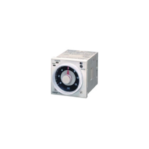
Bộ định thời gian OMRON H3CR-A
-
Mã SP4114
-
Thương hiệu
-
Xuất xứJAPAN
-
Bảo hành12 THÁNG

Bộ định thời gian OMRON H3CR-A
Công ty TNHH Ngân Anh Phát chuyên cung cấp dòng sản phẩm Bộ định thời gian OMRON H3CR-A chính hãng xuất xứ Japan tại thị trường Việt Nam.
Đặc điểm nổi bật của Bộ định thời gian OMRON H3CR-A:
• Dải nguồn cấp AC/DC rộng giúp giảm đáng kể số lượng mẫu bộ hẹn giờ cần lưu trữ.
• Phạm vi ứng dụng rộng với nhiều chế độ hoạt động, tám chế độ cho các mẫu 11 chân và năm chế độ cho các mẫu 8 chân.
• Thiết kế thân thiện với môi trường với mức tiêu thụ dòng điện thấp.
• Kiểm tra trình tự dễ dàng với các đầu ra tức thời khi giá trị cài đặt bằng 0.
• Chiều dài 75 mm hoặc ít hơn khi lắp đặt trên bảng điều khiển với ổ cắm P3G-08 (H3CR-A8E, 100 đến 240 VAC, 100 đến 125 VDC).
• Có sẵn các mẫu đầu vào PNP.
• Tiêu chuẩn: UL, CSA, NK, LR, CCC, EN 61812-1 và CE Marking.

Thông số kỹ thuật
General
| Item | H3CR-A/-AS/-A-301 | H3CR-AP | H3CR-A8/-A8S/-A8-301 | H3CR-A8E |
|---|---|---|---|---|
| Operating mode | A: ON-delay B: Flicker OFF start B2: Flicker ON start C: Signal ON/OFF-delay D: Signal OFF-delay E: Interval G: Signal ON/OFF-delay J: One-shot |
A: ON-delay (power supply start) B: Flicker OFF start (power supply start) B2: Flicker ON start (power supply start) E: Interval (power supply start) J: One-shot (power supply start) |
||
| Pin type | 11-pin | 8-pin | ||
| Input type | No-voltage input | Voltage input | --- | |
| Time-limit output type | H3CR-A/-A8/-AP/-A-301/-A8-301: Relay output (DPDT) H3CR-AS/-A8S: Transistor output (NPN/PNP universal) *1 |
Relay output (SPDT) |
||
| Instantaneous output type | --- | Relay output (SPDT) |
||
| Mounting method | DIN track mounting, surface mounting, and flush mounting | |||
| Approved standards | UL508 *2, CSA C22.2 No.14, NK, Lloyds, CCC: GB/T 14048.5 *3 Conforms to EN61812-1 and IEC60664-1 (VDE0110) 4kV/2. |
|||
*1. The internal circuits are optically isolated from the output. This enables universal application as NPN or PNP transistor.
For details, refer to your OMRON website.
*2. Surrounding air temperature: 0°C to 40°C
*3. CCC certification requirements
| Recommended fuse | Contact Output: 0216005 (250 VAC, 5 A), manufactured by Littelfuse Transistor Output: 0216.100 (250 VAC, 100 mA) manufactured by Littelfuse |
|---|---|
| Rated operating voltage Ue Rated operating current Ie |
Contact Output: AC-15: Ue: 250 VAC, Ie: 3 A AC-13: Ue: 250 VAC, Ie: 5 A DC-13: Ue: 30 VDC, Ie: 0.5 A Transistor Output: DC-13: Ue: 30 VDC, Ie: 0.1 A |
| Rated insulation voltage | 250 V |
| Rated impulse withstand voltage (altitude: 2,000 m max.) |
4 kV (at 240 VAC) |
| Conditional short-circuit current | 1000 A |
Time Ranges
Note: When the time setting knob is turned below "0" until the point where the time setting knob stops, the output will
operate instantaneously at all time range settings.
For details, refer to your OMRON website.
Standard (0.05-s to 300-h) Models
| Time unit | s (sec) | ×10 s (10 sec) | min (min) | ×10 min (10 min) | h (hrs) | ×10 h (10 hrs) | |
|---|---|---|---|---|---|---|---|
| Full scale setting |
1.2 | 0.05 to 1.2 | 1.2 to 12 | 0.12 to 1.2 | 1.2 to 12 | 0.12 to 1.2 | 1.2 to 12 |
| 3 | 0.3 to 3 | 3 to 30 | 0.3 to 3 | 3 to 30 | 0.3 to 3 | 3 to 30 | |
| 12 | 1.2 to 12 | 12 to 120 | 1.2 to 12 | 12 to 120 | 1.2 to 12 | 12 to 120 | |
| 30 | 3 to 30 | 30 to 300 | 3 to 30 | 30 to 300 | 3 to 30 | 30 to 300 | |
Double (0.1-s to 600-h) Models
| Time unit | s (sec) | ×10 s (10 sec) | min (min) | ×10 min (10 min) | h (hrs) | ×10 h (10 hrs) | |
|---|---|---|---|---|---|---|---|
| Full scale setting |
2.4 | 0.1 to 2.4 | 2.4 to 24 | 0.24 to 2.4 | 2.4 to 24 | 0.24 to 2.4 | 2.4 to 24 |
| 6 | 0.6 to 6 | 6 to 60 | 0.6 to 6 | 6 to 60 | 0.6 to 6 | 6 to 60 | |
| 24 | 2.4 to 24 | 24 to 240 | 2.4 to 24 | 24 to 240 | 2.4 to 24 | 24 to 240 | |
| 60 | 6 to 60 | 60 to 600 | 6 to 60 | 60 to 600 | 6 to 60 | 60 to 600 | |
Ratings
| Rated supply voltage *1 *2 *5 |
100 to 240 VAC (50/60 Hz)/100 to 125 VDC, 24 to 48 VAC (50/60 Hz)/12 to 48 VDC (24 to 48 VAC/VDC for H3CR-A8E) *3 |
|---|---|
| Operating voltage range | 85% to 110% of rated voltage (90% to 110% at 12 to 48 VDC) |
| Power reset | Minimum power-opening time: 0.1 s |
| Input *6 | No-voltage Input ON impedance: 1 kΩ max. ON residual voltage: 1 V max. OFF impedance: 100 kΩ min. Voltage Input Max. permissible capacitance between inputs lines (terminals 6 and 7): 1,200 pF Load connectable in parallel with inputs (terminals 6 and 7). 100 to 240 VAC/100 to 125 VDC High (logic) level: 85 to 264 VAC/85 to 137.5 VDC Low (logic) level: 0 to 10 VAC/0 to 10 VDC 24 to 48 VAC/12 to 48 VDC High (logic) level: 20.4 to 52.8 VAC/10.8 to 52.8 VDC Low (logic) level: 0 to 2.4 VAC/0 to 1.2 VDC |
| Power consumption | H3CR-A/-A8 100 to 240 VAC/100 to 125 VDC (When at 240 VAC, 60 Hz) Relay ON: approx. 2.0 VA (1.6 W), Relay OFF: approx. 1.3 VA (1.1 W) 24 to 48 VAC/12 to 48 VDC (When at 24 VDC) Relay ON: approx. 0.8 W, Relay OFF: approx. 0.2 W H3CR-AP *3 100 to 240 VAC/100 to 125 VDC (When at 240 VAC, 60 Hz) Relay ON: approx. 2.5 VA (2.2 W) *4, Relay OFF: approx. 1.8 VA (1.7 W) *4 24 to 48 VAC/12 to 48 VDC (When at 24 VDC) Relay ON: approx. 0.9 W *4, Relay OFF: approx. 0.3 W *4 H3CR-A8E 100 to 240 VAC/100 to 125 VDC (When at 240 VAC, 60 Hz) Relay ON/OFF: approx. 2 VA (0.9 W) 24 to 48 VAC/VDC (When at 24 VDC) Relay ON/OFF: approx. 0.9 W H3CR-AS/-A8S 24 to 48 VAC/12 to 48 VDC (When at 24 VDC) Output ON: 0.3 W, Output OFF: 0.2 W |
| Control outputs | Models with Contact Outputs H3CR-A/-A8/-AP 5A at 250 VAC/30 VDC, 0.15A at 125 VDC, resistive load (cosφ = 1) Minimum applied load: 10mA at 5 VDC (failure level: P reference value) Contact materials: Ag-alloy H3CR-A8E 5A at 250 VAC/30 VDC, 0.15A at 125 VDC, resistive load (cosφ = 1) Minimum applied load: 10mA at 5 VDC (failure level: P reference value) Contact materials: AgSnIn Transistor output: Open collector(NPN/PNP) H3CR-AS/-A8S 100 mA max at 30 VDC max., residual voltage: 2 VDC max. |
*1. DC ripple rate: 20% max. (A single-phase, full-wave-rectification power supply can be used).
*2. Do not use an inverter output as the power supply. Refer to your OMRON website for details.
*3. Models with 24-to-48-VAC or 12-to-48-VDC power supply have inrush current. Caution is thus required when turning
ON and OFF power to the Timer with a non-contact output from a device such as a sensor. (Models with an inrush
current of approximately 50 mA and a 24-VDC power supply are available (the H3CR-A-302 and H3CR-A8-302).)
For details, consult your OMRON sales representative.
*4. The values are for when the terminals 2 and 7 and terminals 10 and 6 are short-circuited, and include the
consumption current of the input circuit.
*5. Refer to your OMRON website when using the Timer together with a 2-wire AC proximity sensor.
*6. For details, see Input Connections: No-voltage Input Signal Levels on Catalog, and Input Connections: Voltage Input
Signal Levels on Catalog.
Characteristics
| Accuracy of operating time |
±0.2% FS max. (±0.2%±10 ms max. in a range of 1.2 s or 3 s) |
|---|---|
| Setting error | ±5% FS ±50 ms *1 |
| Reset time | Min. power-opening time: 0.1 s max. Min. pulse width: 0.05 s (H3CR-A/-AS) |
| Reset voltage | 10% max. of rated supply voltage |
| Influence of voltage *2 | ±0.2% FS max. (±0.2%±10 ms max. in a range of 1.2 s or 3 s) |
| Influence of temperature | ±1% FS max. (±1%±10 ms max. in a range of 1.2 s or 3 s) |
| Insulation resistance | 100 MΩ min. (at 500 VDC) |
| Dielectric strength | 2,000 VAC (1,000 VAC for H3CR-A[]S), 50/60 Hz for 1 min (between current-carrying metal parts and exposed non-current-carrying metal parts) 2,000 VAC (1,000 VAC for H3CR-A[]S), 50/60 Hz for 1 min (between control output terminals and operating circuit) 2,000 VAC, 50/60 Hz for 1 min (between contacts of different polarities) 1,000 VAC, 50/60 Hz for 1 min (between contacts not located next to each other) 2,000 VAC, 50/60 Hz for 1 min (between input and control output terminals and operation circuit) for H3CR-AP |
| Impulse withstand voltage |
5 kV (between power terminals) for 100 to 240 VAC/100 to 125 VDC, 1 kV for 24 to 48 VAC/12 to 48 VDC 5 kV (between current-carrying terminal and exposed non-current-carrying metal parts) for 100 to 240 VAC/100 to 125 VDC, 1.5 kV for 24 to 48 VAC/12 to 48 VDC and 24 to 48 VAC/VDC |
| Noise immunity | ±1.5 kV (between power terminals) and ±600 V (between no-voltage input terminals), square-wave noise by noise simulator (pulse width: 100 ns/1 μs, 1-ns rise) |
| Static immunity | Malfunction: 8 kV Destruction: 15 kV |
| Vibration resistance | Destruction: 10 to 55 Hz with 0.75-mm single amplitude each in 3 directions for 2 hours each Malfunction: 10 to 55 Hz with 0.5-mm single amplitude each in 3 directions for 10 minutes each |
| Shock resistance | Destruction: 1,000 m/s2 3 times each in 6 directions Malfunction: 100 m/s2 3 times each in 6 directions |
| Ambient temperature | Operating: -10°C to 55°C (with no icing) Storage: -25°C to 65°C (with no icing) |
| Ambient humidity | Operating: 35% to 85% |
| Life expectancy *4 | Mechanical: 20,000,000 operations min. (under no load at 1,800 operations/h) Electrical: 100,000 operations min. (5 A at 250 VAC, resistive load at 1,800 operations/h) *3 |
| EMC | (EMI) EN61812-1 Emission Enclosure: EN55011 Group 1 class A Emission AC Mains: EN55011 Group 1 class A (EMS) EN61812-1 Immunity ESD: IEC61000-4-2 Immunity RF-interference: IEC61000-4-3 Immunity Burst: IEC61000-4-4 Immunity Surge: IEC61000-4-5 Immunity Conducted Disturbance: IEC61000-4-6 Immunity Voltage Dip/Interruption: IEC61000-4-11 |
| Case color | Light gray (Munsell 5Y7/1) |
| Degree of protection | IP40 (panel surface) |
| Weight | Approx. 90 g |
*1. The value is ±5% FS +100 ms to −0 ms max. when the C, D, or G mode signal of the H3CR-AP is OFF.
*2. The influence of voltage of the H3CR-A8E (24 to 48 VAC/12 to 48 VDC) is ±2.0% FS max. with a single-phase power
supply with fullwave rectification.
*3. Refer to the Life-test Curve (Reference).
*4. Contact output only.
Life-test Curve (Reference)
Reference:
A maximum current of 0.15 A can be switched at 125 VDC (cosφ = 1) and a maximum current of 0.1A can be switched at 125V DC and L/R = 7ms.
In both cases, a life of 100,000 operations can be expected.


- Đ3, Đường Đồng Khởi, Tổ 23, Khu phố 35, Phường Tam Hiệp, Tỉnh Đồng Nai, Việt Nam
- (+84) 2513 857 563
- info@ngananhphat.com, sales@ngananhphat.com
- www.ngananhphat.com

Giấy phép đăng ký kinh doanh số : 3600955737 do Sở Kế Hoạch & Đầu Tư Tỉnh Đồng Nai cấp ngày 19/11/2007.