


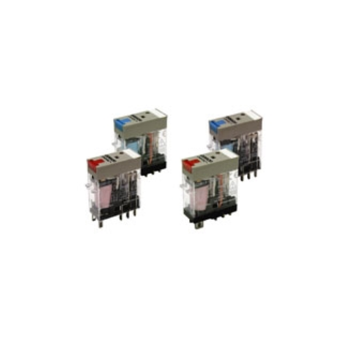
Rơ le trung gian OMRON G2R
-
Mã SP3968
-
Thương hiệu
-
Xuất xứJAPAN
-
Bảo hành12 THÁNG

Rơ le trung gian OMRON G2R
Công ty TNHH Ngân Anh Phát chuyên cung cấp dòng sản phẩm Rơ le trung gian OMRON G2R chính hãng xuất xứ Japan tại thị trường Việt Nam.
Đặc điểm nổi bật của Rơ le trung gian OMRON G2R
• Giảm công việc đi dây đến 60% khi kết hợp với ổ cắm Push-In Plus P2RF-[]-PU (theo đo thực tế của OMRON).
• Có sẵn các mẫu có nút kiểm tra có thể khóa.
• Được trang bị chỉ báo hoạt động cơ học tích hợp.
• Có bảng tên.
• Loại AC được trang bị chức năng tự chẩn đoán ngắt cuộn (kiểu LED).
• Công suất chuyển mạch cao (1 cực: 10 A).
Thông số kỹ thuật
Coil Ratings
| Rated voltage | Rated current* | Coil resistance |
Coil inductance (H) (ref. value) |
Must operate voltage |
Must release voltage |
Max. voltage |
Power consumption (approx.) |
|||
|---|---|---|---|---|---|---|---|---|---|---|
| 50 Hz | 60 Hz | Armature OFF |
Armature ON |
% of rated voltage | ||||||
| AC | 24 V | 43.5 mA | 37.4 mA | 253 Ω | 0.81 | 1.55 | 80% max. | 30% max. | 110% | 0.9 VA at 60 Hz |
| 48 V | 21.8 mA | 18.8 mA | 1,040 Ω | 3.12 | 6.17 | |||||
| 110 V | 9.5 mA | 8.2 mA | 5,566 Ω | 13.33 | 26.83 | |||||
| 120 V | 8.6 mA | 7.5 mA | 7,286 Ω | 16.13 | 32.46 | |||||
| 230 V | 4.4 mA | 3.8 mA | 27,172 Ω | 72.68 | 143.9 | |||||
| 240 V | 4.2 mA | 3.7 mA | 27,800 Ω | 90.58 | 182.34 | |||||
| Rated voltage | Rated current* | Coil resistance |
Coil inductance (H) (ref. value) |
Must operate voltage |
Must release voltage |
Max. voltage |
Power consumption (approx.) |
||
|---|---|---|---|---|---|---|---|---|---|
| Armature OFF |
Armature ON |
% of rated voltage | |||||||
| DC | 6 V | 87.0 mA | 69 Ω | 0.25 | 0.48 | 70% max. | 15% min. | 110% | 0.53 W |
| 12 V | 43.2 mA | 278 Ω | 0.98 | 2.35 | |||||
| 24 V | 21.6 mA | 1,113 Ω | 3.6 | 8.25 | |||||
| 48 V | 11.4 mA | 4,220 Ω | 15.2 | 29.82 | |||||
Note:
1. The rated current and coil resistance are measured at a coil temperature of 23°C with tolerances of
+15%/-20% for the AC rated current and ±10% for the DC coil resistance.
2. The AC coil resistance and inductance values are reference values only (at 60 Hz).
3. Operating characteristics were measured at a coil temperature of 23°C.
4. The maximum voltage is the maximum possible value of the voltage that can be applied to the relay coil.
It is not the maximum voltage that can be applied continuously.
Contact Ratings
| Number of poles | 1 pole | 2 poles | ||
|---|---|---|---|---|
| Load | Resistive load (cosΦ = 1) |
Inductive load (cosΦ = 0.4; L/R = 7 ms) |
Resistive load (cosΦ = 1) |
Inductive load (cosΦ = 0.4; L/R = 7 ms) |
| Rated load | 10 A at 250 VAC; 10 A at 30 VDC |
7.5 A at 250 VAC; 5 A at 30 VDC |
5 A at 250 VAC; 5 A at 30 VDC |
2 A at 250 VAC; 3 A at 30 VDC |
| Rated carry current | 10 A | 5 A | ||
| Max. switching voltage | 440 VAC, 125 VDC | 380 VAC, 125 VDC | ||
| Max. switching current | 10 A | 5 A | ||
| Max. switching power | 2,500 VA, 300 W | 1,875 VA, 150 W | 1,250 VA, 150 W | 500 VA, 90 W |
| Failure rate (reference value) * | 100 mA at 5 VDC | 10 mA at 5 VDC | ||
Note: P level: λ60 = 0.1 x 10⁻⁶/operation
*This value was measured at a switching frequency of 120 operations per minute.
Characteristics
| Item | 1 pole | 2 poles |
|---|---|---|
| Contact configration | SPDT | |
| Contact structure | Single | |
| Contact resistance | 100 mΩ max. | |
| Operate (set) time | 15 ms max. | |
| Release (reset) time | AC: 10 ms max.; DC: 5 ms max. (w/built-in diode: 20 ms max.) |
AC: 15 ms max.; DC: 10 ms max. (w/built-in diode: 20 ms max.) |
| Max. operating frequency |
Mechanical: 18,000 operations/hr Electrical: 1,800 operations/hr (under rated load) |
|
| Insulation resistance | 1,000 MΩ min. (at 500 VDC) | |
| Dielectric strength * | 5,000 VAC, 50/60 Hz for 1 min between coil and contacts; 1,000 VAC, 50/60 Hz for 1 min between contacts of same polarity |
5,000 VAC, 50/60 Hz for 1 min between coil and contacts; 3,000 VAC, 50/60 Hz for 1 min between contacts of different polarity 1,000 VAC, 50/60 Hz for 1 min between contacts of same polarity |
| Vibration resistance | Destruction: 10 to 55 to 10 Hz, 0.75 mm single amplitude (1.5 mm double amplitude) Malfunction: 10 to 55 to 10 Hz, 0.75 mm single amplitude (1.5 mm double amplitude) |
|
| Shock resistance | Destruction: 1,000 m/s2 Malfunction: 200 m/s2 when energized; 100 m/s2 when not energized |
|
| Endurance | Mechanical: AC coil: 10,000,000 operations min.; DC coil: 20,000,000 operations min. (at 18,000 operations/hr) Electrical: 100,000 operations min. (at 1,800 operations/hr under rated load) (DC coil type) |
|
| Ambient temperature | Operating: -40°C to 70°C (with no icing or condensation) | |
| Ambient humidity | Operating: 5% to 85% | |
| Weight | Approx. 20 g | |
Note: Values in the above table are the initial values.
*These values are relay only. Prease refer to the “Products Related to Common Sockets and DIN Tracks Data Sheet” for connecting sockets.
Approved Standards
UL 508 (File No. E41643)
| Model | Contact form | Coil ratings | Contact ratings | Operations |
|---|---|---|---|---|
| G2R-1-S (S) | SPDT | 5 to 110 VDC 6 to 240 VAC |
10 A, 30 VDC (resistive) 10 A, 250 VAC (general use) |
100 × 103 |
| TV-3 (NO contact only) | 25 × 103 | |||
| G2R-2-S (S) | DPDT | 5 A, 30 VDC (resistive) 5 A, 250 VAC (general use) |
100 × 103 | |
| TV-3 (NO contact only) | 25 × 103 |
CSA 22.2 No.0, No.14 (File No. LR31928)
| Model | Contact form | Coil ratings | Contact ratings | Operations |
|---|---|---|---|---|
| G2R-1-S (S) | SPDT | 5 to 110 VDC 6 to 240 VAC |
10 A, 30 VDC (resistive) 10 A, 250 VAC (general use) |
100 × 103 |
| TV-3 (NO contact only) | 25 × 103 | |||
| G2R-2-S (S) | DPDT | 5 A, 30 VDC (resistive) 5 A, 250 VAC (general use) |
100 × 103 | |
| TV-3 (NO contact only) | 25 × 103 |
IEC/VDE (Certificate No. 40015012 EN 61810-1)
| Contact form | Coil ratings | Contact ratings | Operations |
|---|---|---|---|
| 1 pole | 6, 12, 24, 48 VDC 24, 110, 120, 230, 240 VAC |
5 A, 440 VAC (cosφ = 1.0) 10 A, 250 VAC (cosφ = 1.0) 10 A, 30 VDC (0 ms) |
100 × 103 |
| 2 poles | 6, 12, 24, 48 VDC 24, 110, 120, 230, 240 VAC |
5 A, 250 VAC (cosφ =1.0) 5 A, 30 VDC (0 ms) |
100 × 103 |
LR
| Number of poles | Coil ratings | Contact ratings | Operations |
|---|---|---|---|
| 1 pole | 5 to 110 VDC 6 to 240 VDC |
10 A, 250 VAC (general use) 7.5 A, 250 VAC (PF0.4) 10 A, 30 VDC (resistive) 5A, 30VDC (L/R=7ms) |
100 × 103 |
| 2 poles | 5 to 110 VDC 6 to 240 VDC |
5 A, 250 VAC (general use) 2 A, 250 VAC (PF0.4) 5 A, 30 VDC (resistive) 3A, 30VDC (L/R=7ms) |
100 × 103 |
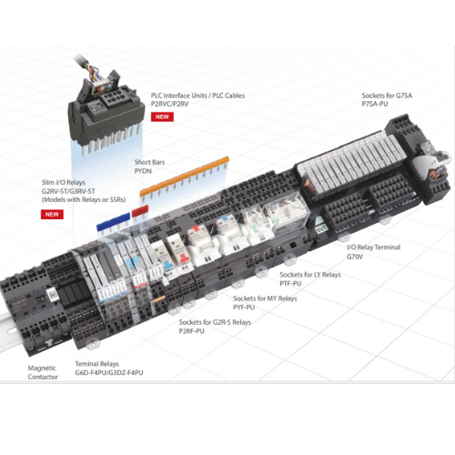
Accessories (Order Separately)
Socket Characteristics
| Model | Rated carry current |
Dielectric strength | Insulation resistance* |
Remarks |
|---|---|---|---|---|
| P2RF-05-PU | 10 A | Between contact terminals of same polarity: 1,000 VAC for 1 min |
1,000 MΩ min. | |
| Between coil and contact terminals: 4,000 VAC for 1 min | ||||
| P2RF-08-PU | 6 A | Between contact terminals of different polarity: 3,000 VAC for 1 min |
1,000 MΩ min. | |
| Between contact terminals of same polarity: 1,000 VAC for 1 min |
||||
| Between coil and contact terminals: 4,000 VAC for 1 min | ||||
| P2RFZ-05(-E) | 10 A | Between contact terminals of same polarity: 1,000 VAC for 1 min |
1,000 MΩ min. | |
| Between coil and contact terminals: 4,000 VAC for 1 min | ||||
| P2RFZ-08(-E) | 6 A | Between contact terminals of different polarity: 3,000 VAC for 1 min |
1,000 MΩ min. | |
| Between contact terminals of same polarity: 1,000 VAC for 1 min |
||||
| Between coil and contact terminals: 4,000 VAC for 1 min | ||||
| P2R-05P | 10 A | Between contact terminals of same polarity: 1,000 VAC for 1 min |
1,000 MΩ min. | |
| Between coil and contact terminals: 4,000 VAC for 1 min | ||||
| P2R-08P | 5 A | Between contact terminals of different polarity: 3,000 VAC for 1 min |
1,000 MΩ min. | |
| Between contact terminals of same polarity: 1,000 VAC for 1 min |
||||
| Between coil and contact terminals: 4,000 VAC for 1 min | ||||
| P2R-057P | 10 A | Between contact terminals of same polarity: 1,000 VAC for 1 min |
1,000 MΩ min. | |
| Between coil and contact terminals: 5,000 VAC for 1 min | ||||
| P2R-087P | 5 A | Between contact terminals of different polarity: 3,000 VAC for 1 min |
1,000 MΩ min. | |
| Between contact terminals of same polarity: 1,000 VAC for 1 min |
||||
| Between coil and contact terminals: 5,000 VAC for 1 min | ||||
| P2R-05A | 10 A | Between contact terminals of same polarity: 1,000 VAC for 1 min |
1,000 MΩ min. | |
| Between ground terminals: 1,500 VAC for 1 min | ||||
| Between coil and contact terminals: 4,000 VAC for 1 min | ||||
| P2R-08A | 5 A | Between contact terminals of different polarity: 3,000 VAC for 1 min |
1,000 MΩ min. | |
| Between contact terminals of same polarity: 1,000 VAC for 1 min |
||||
| Between ground terminals: 1,500 VAC for 1 min | ||||
| Between coil and contact terminals: 4,000 VAC for 1 min |
* The insulation resistance was measured with a 500-VDC insulation resistance meter at the same places as those used for
measuring the dielectric strength.
SẢN PHẨM LIÊN QUAN


- Đ3, Đường Đồng Khởi, Tổ 23, Khu phố 35, Phường Tam Hiệp, Tỉnh Đồng Nai, Việt Nam
- (+84) 2513 857 563
- info@ngananhphat.com, sales@ngananhphat.com
- www.ngananhphat.com

Giấy phép đăng ký kinh doanh số : 3600955737 do Sở Kế Hoạch & Đầu Tư Tỉnh Đồng Nai cấp ngày 19/11/2007.