
- AUTOMATION
- MACHINE DEVICE
- CONSTRUCT DEVICE
- FACTORY DEVICE
- TESTING DEVICE
- TENSION MEASUREMENT
- TRACTION MEASUREMENT
- TORQUE MEASUREMENT
- RPM MEASUREMENT
- THICKNESS MEASUREMENT
- STIFFNESS MEASUREMENT
- DISTANCE MEASUREMENT
- VISCOSITY MEASUREMENT
- FLOW/LEVEL MEASUREMENT
- DEPTH MEASUREMENT
- DIAL INDICATOR
- MICROMETER
- CALIPER
- MEASUREMENT ACCESSORIES
- MICROSCOPE
- MAGNIFIER
- TENSION TESTOR
- LINEAR SCALE
- TEMPERATURE MEASUREMENT
- WIND MEASUREMENT
- SOUND MEASUREMENT
- SPEED MEASUREMENT
- DENSITY MEASUREMENT
- CURRENT MEASUREMENT
- WEIGHT MEASUREMENT
- CALIPERS
- ENVICONMENT DEVICE
- SOLAR PRODUCTS
-
 AUTOMATION
CategoryBrand
AUTOMATION
CategoryBrand


-
 MACHINE DEVICE
-
 CONSTRUCT DEVICE
-
 FACTORY DEVICE
-
 TESTING DEVICE
Category
TESTING DEVICE
Category- TENSION MEASUREMENT
- TRACTION MEASUREMENT
- TORQUE MEASUREMENT
- RPM MEASUREMENT
- THICKNESS MEASUREMENT
- STIFFNESS MEASUREMENT
- DISTANCE MEASUREMENT
- VISCOSITY MEASUREMENT
- FLOW/LEVEL MEASUREMENT
- DEPTH MEASUREMENT
- DIAL INDICATOR
- MICROMETER
- CALIPER
- MEASUREMENT ACCESSORIES
- MICROSCOPE
- MAGNIFIER
- LINEAR SCALE
- TEMPERATURE MEASUREMENT
- WIND MEASUREMENT
- SOUND MEASUREMENT
- SPEED MEASUREMENT
- DENSITY MEASUREMENT
- CURRENT MEASUREMENT
- WEIGHT MEASUREMENT
Brand


-
 ENVICONMENT DEVICE
Brand
ENVICONMENT DEVICE
Brand


- Home Page
- Product
- AUTOMATION
- TIMERS
- Twin Timer OMRON H3DT-F
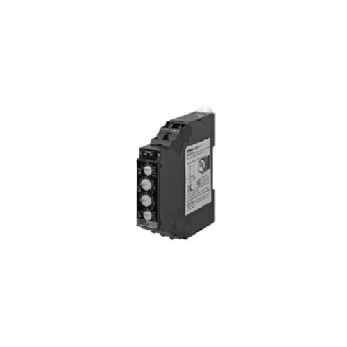
Twin Timer OMRON H3DT-F
-
Product No4108
-
Brand
-
OriginJAPAN
-
Guarantee12 MONTHS
Our Value Design Products Increase the Value of Your Control Panels. Switch between flicker-OFF or flicker-ON start mode.

Twin Timer OMRON H3DT-F
Ngan Anh Phat Co., Ltd specializes in providing genuine products Twin Timer OMRON H3DT-F from the manufacturer Omron, originating from Japan, to the Vietnamese market.
Outstanding features of the Twin Timer OMRON H3DT-F
-
Diverse timing modes: The H3DT-F supports various timing modes, such as ON delay, instantaneous, and other flexible timing modes.
-
Precise time adjustment: The timing can be adjusted accurately, making it suitable for systems that require high precision.
-
Easy display: The easy-to-read LCD screen allows users to monitor and adjust the timing conveniently.
-
Compact and durable design: The relay has a compact design, making it easy to install in control panels without taking up much space, while ensuring durability in harsh working conditions.
-
High load capacity: The H3DT-F can handle large loads, making it suitable for a wide range of industrial applications.
-
Versatile inputs and outputs: Supports flexible input and output options, facilitating integration into various control systems.
-
Safety protection features: Equipped with protection functions to ensure the safety of the system and devices during operation.
-
Easy installation and operation: The user-friendly interface makes installation and operation easy, suitable for both novice and experienced users.
-
Long lifespan: The relay has a long lifespan, reducing maintenance and replacement costs over time.
Specifications
Time Ranges
| Time range setting | 0.1 s | 1 s | 10 s | 1 min | 10 min | 1 h | 10 h | 100 h |
|---|---|---|---|---|---|---|---|---|
| Set time range | 0.1 to 1.2 s | 1 to 12 s | 10 to 120 s | 1 to 12 min | 10 to 120 min |
1 to 12 h | 10 to 120 h | 100 to 1,200 h |
| Scale numbers | 12 | |||||||
Ratings
| Power supply voltage *1 | 24 to 240 VAC/DC, 50/60 Hz *2 | |
|---|---|---|
| Allowable voltage fluctuation range | 85% to 110% of rated voltage | |
| Power reset | Minimum power-OFF time: 0.1 s | |
| Reset voltage | 10% of rated voltage | |
| Power consumption | H3DT-F | At 240 VAC: 1.9VA max., at 240 VDC: 0.6W max., at 24 VDC: 0.3W max. |
| Rated Insulation Voltage | 250 VAC | |
| Control output | Contact output: 5 A at 250 VAC with resistive load (cosφ = 1), 5 A at 30 VDC with resistive load, 0.15 A max. at 125 VDC with resistive load, 0.1 A max. at 125 VDC with L/R of 7 ms. The minimum applicable load is 10 mA at 5 VDC (P reference value). Contact materials: Ag-alloy (Recommended fuse: BLN5 (Littelfuse) or 0216005MXEP) |
|
| Ambient operating temperature | -20 to 60°C (with no icing) | |
| Storage temperature | -40 to 70°C (with no icing) | |
| Surrounding air operating humidity |
25% to 85% | |
*1. When using a 24-VDC power supply voltage, there will be an inrush current of approximately 0.5 A.
Allow for this inrush current when turning ON and OFF the power supply to the Timer with device with a solid-state output,
such as a sensor.
*2. DC ripple: 20% max.
Characteristics
| Accuracy of operating time | ±1% of FS max. (±1% ±10 ms max. at 1.2-s range) | |
|---|---|---|
| Setting error | ±10% of FS ±0.05 s max. | |
| Influence of voltage | ±0.5% of FS max. (±0.5% ±10 ms max. at 1.2-s range) | |
| Influence of temperature | ±2% of FS max. (±2% ±10 ms max. at 1.2-s range) | |
| Insulation resistance | 100 MΩ min. at 500 VDC | |
| Dielectric strength | Between charged metal part and operating section: 2,900 VAC 50/60 Hz for 1 min. Between control output terminals and operating circuit: 2,000 VAC 50/60 Hz for 1 min. Between contacts not located next to each other: 1,000 VAC 50/60 Hz for 1 min. |
|
| Impulse withstand test voltage | 5 kV between power terminals, 7.4 kV between conductor terminal and operating section |
|
| Noise immunity | Square-wave noise generated by noise simulator (pulse width: 100 ns/1 μs, 1-ns rise): ±1.5 kV |
|
| Static immunity | Malfunction: 4 kV, Destruction: 8 kV | |
| Vibration resistance |
Destruction | 0.75-mm single amplitude at 10 to 55 Hz for 2 h each in 3 directions |
| Malfunction | 0.5-mm single amplitude at 10 to 55 Hz for 10 min each in 3 directions | |
| Shock resistance |
Destruction | 1,000 m/s2 3 times each in 6 directions |
| Malfunction | 100 m/s2 3 times each in 6 directions | |
| Life expectancy |
Mechanical | 10 million operations min. (under no load at 1,800 operations/h) |
| Electrical | 100,000 operations min. (5 A at 250 VAC, resistive load at 360 operations/h) | |
| Degree of protection | IP30 (Terminal block: IP20) | |
| Weight | Approx. 90 g | |
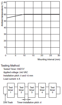
Relation between H3DT Ambient Temperature and Mounting Interval (Reference Values)
The relation between the ambient temperature and mounting interval is shown in the following graph.
If the Timer is used at 55°C or higher with a mounting interval that is smaller than that shown in the following diagram, the temperature inside the Timer will increase, reducing the life expectancy of internal parts.
Applicable standards
| Safety standards | cULus: UL 508/CSA C22.2 No. 14 EN 61812-1: Pollution degree 2, Overvoltage category III CCC: GB/T 14048.5 Pollution degree 2, Overvoltage category III * LR: Category ENV1.2 |
|---|---|
| EMC | (EMI) EN 61812-1 Radiated Emissions: EN 55011 class B Emission AC Mains: EN 55011 class B Harmonic Current: EN 61000-3-2 Voltage Fluctuations and Flicker: EN 61000-3-3 (EMS) EN 61812-1 Immunity ESD: EN 61000-4-2 Immunity RF-interference: EN 61000-4-3 Immunity Burst: EN 61000-4-4 Immunity Surge: EN 61000-4-5 Immunity Conducted Disturbance: EN 61000-4-6 Immunity Voltage Dip/Interruption: EN 61000-4-11 |
* CCC certification requirements
| Rated operating voltage Ue Rated operating current Ie |
AC-15: Ue: 250 VAC, Ie: 3 A AC-13: Ue: 250 VAC, Ie: 5 A DC-13: Ue: 30 VDC, Ie: 0.1 A |
|---|---|
| Rated impulse withstand voltage (altitude: 2,000 m max.) |
4 kV (at 240 VAC) |
| Conditional short-circuit current | 1,000 A |
I/O
| Input | None | |
|---|---|---|
| Output | Control output | Output is turned ON/OFF according to the time set on the ON time setting dial and OFF time setting dial. |


- D3, Dong Khoi, Group 23, Quarter 35, Tam Hiep Ward, Dong Nai Province, Vietnam
- (+84) 2513 857 563
- info@ngananhphat.com, sales@ngananhphat.com
- www.ngananhphat.com

Giấy phép đăng ký kinh doanh số : 3600955737 do Sở Kế Hoạch & Đầu Tư Tỉnh Đồng Nai cấp ngày 19/11/2007.