


Solid-state Timer OMRON H3DS
-
Product No4124
-
Brand
-
OriginJAPAN
-
Guarantee12 MONTHS
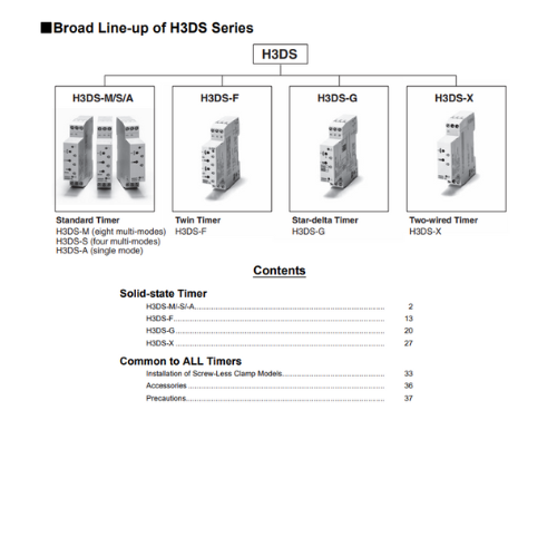
DIN Track Mounted, Standard 17.5-mm Width Timer Range

Solid-state Timer OMRON H3DS
Ngan Anh Phat Co., Ltd specializes in providing genuine products Solid-state Timer OMRON H3DS from the manufacturer Omron, originating from Japan, to the Vietnamese market.
Outstanding features of the Solid-state Timer OMRON H3DS:
• A wide AC/DC power supply range (24 to 230 VAC/ 24 to 48 VDC) reduces the number of timer models kept in stock. (24 to 230 VAC/VDC with H3DS-XL[])
• Smart Dial/Selector-locking Mechanism: Prevents the dials and selectors on the Timer’s front panel from being inadvertently operated or being operated without authorization. The lock can only be unlocked and locked with an optional pen-type Lock Key.
• Screw-Less Clamp type available. (H3DS-[]LC)
• Sticker provided for easy timer identification and management.
• Terminal clamp left open when delivered (screw terminal type).
• Finger protection terminal block to meet VDE0106/P100.
• Enables easy sequence checks through instantaneous outputs for a zero set value at any time range.
• Incorporates environment-friendly, cadmium-free contacts.
• Conforms to EN61812-1 and IEC60664-1 4 kV/2 for Low Voltage, and EMC Directives.
Specifications
H3DS-M/-S/-A
General
| Item | H3DS-ML[] | H3DS-SL[] | H3DS-AL[] |
|---|---|---|---|
| Operating mode | A: ON-delay (Signal or Power) B: Flicker OFF start (Signal or Power) B2: Flicker ON start (Signal or Power) C: Signal ON/OFF-delay D: Signal OFF-delay E: Interval (Signal or Power) G: Signal ON/OFF-delay J: One-shot (Signal or Power) |
A: ON-delay B2: Flicker ON start E: Interval J: One-shot |
A: ON-delay (fixed) |
| Input type | Voltage input | --- | |
| Output type | Relay: SPDT | ||
| External connections | Screw terminal, Screw-Less Clamp | ||
| Terminal block | Screw terminal type: Clamps two 2.5-mm2 max. bar terminals without sleeves. Screw-Less Clamp type: Clamps two 1.5-mm2 max. bar terminals without sleeves. |
||
| Terminal screw tightening torque |
0.98 Nm max. | ||
| Mounting method | DIN track mounting * | ||
| Attachment | Nameplate label | ||
| Approved standards | UL508, CSA C22.2 No.14 Conforms to EN61812-1, IEC60664-1 4 kV/2, VDE0106/P100 |
||
* Can be mounted to 35-mm DIN Track with a plate thickness of 1 to 2.5 mm.
Time Ranges
| Time scale display | Time range |
|---|---|
| 0.1 s | 0.1 to 1.2 s |
| 1 s | 1 to 12 s |
| 0.1 m | 0.1 to 1.2 min |
| 1 m | 1 to 12 min |
| 0.1 h | 0.1 to 1.2 h |
| 1 h | 1 to 12 h |
| 10 h | 10 to 120 h |
Note: When the time setting dial is set to "0" for any time scale, the output will operate instantaneously.
Ratings
| Rated supply voltage *1, *2 | 24 to 230 VAC (50/60 Hz)/24 to 48 VDC |
|---|---|
| Operating voltage range | 85% to 110% of rated supply voltage |
| Power reset | Minimum power-off time: 0.1 s |
| Reset voltage | 2.4 VAC/DC max. |
| Power consumption *3 | AC: 32 VA max./3.0 W max. (typical: 30 VA/2.7 W) at 230 VAC DC: 0.7 W max. (typical: 0.6 W) at 24 VDC 1.4 W max. (typical: 1.3 W) at 48 VDC |
| Voltage input | Max. permissible capacitance between inputs lines (terminals B1 and A2): 2,000 pF Load connectable in parallel with inputs (terminals B1 and A1). H-level: 20.4 to 253 VAC/20.4 to 52.8 VDC L-level: 0 to 2.4 VAC/DC |
| Control output | Contact output: 5 A at 250 VAC with resistive load (cosφ = 1) 1 A at 250 VAC with inductive load (cosφ = 0.3) 5 A at 30 VDC with resistive load (cosφ = 1) 0.15 A max. at 125 VDC with resistive load, 0.1 A max. at 125 VDC with L/R of 7 ms. The minimum applicable load is 10 mA at 5 VDC (P reference value). Contact materials: Ag-alloy |
| Ambient temperature | Operating: -10°C to 55°C (with no icing) Storage: -25°C to 65°C (with no icing) |
| Ambient humidity | Operating: 35% to 85% |
*1. DC ripple rate: 20% max.
*2. Since an inrush current of 0.5 A will occur when using the power supply voltage at 24 VDC, pay careful attention
when turning on or off the power supply to the Timer with a solid-state output such as a sensor.
*3. The power consumption is for mode A after the Timer counts the time-up time and for the AC input at 50 Hz. The
power consumption of the H3DS-ML includes the input circuit with the B1 and A1 terminals short-circuited.
Characteristics
| Accuracy of operating time |
±1% max. of FS (±1% ±10 ms max. at 1.2-s range) |
|---|---|
| Setting error | ±10% ±50 ms max. of FS |
| Signal input time | 50 ms min. |
| Influence of voltage | ±0.7% max. of FS (±0.7% ±10 ms max. at 1.2-s range) |
| Influence of temperature |
±5% max. of FS (±5%±10 ms max. at 1.2-s range) |
| Insulation resistance | 100 MΩ min. at 500 VDC |
| Dielectric strength | Between current-carrying metal parts and exposed non-current-carrying metal parts: 2,000 VAC for 1 min. Between control output terminals and operating circuit: 2,000 VAC for 1 min. Between contacts not located next to each other: 1,000 VAC for 1 min. |
| Vibration resistance | Malfunction: 0.5-mm single amplitude at 10 to 55 Hz Destruction: 0.75-mm single amplitude at 10 to 55 Hz |
| Shock resistance | Malfunction: 100 m/s2 3 times each in 6 directions Destruction: 1,000 m/s2 3 times each in 6 directions |
| Impulse withstand voltage |
5 kV (between power terminals) 5 kV (between current-carrying metal parts and exposed non-current-carrying metal parts) |
| Noise immunity | Square-wave noise generated by noise simulator (pulse width: 100 ns/1 μs, 1-ns rise) ±1.5 kV |
| Static immunity | Malfunction: 4 kV Destruction: 8 kV |
| Life expectancy | Mechanical: 10 million operations min. (under no load at 1,800 operations/h) Electrical: 100,000 operations min. (5 A at 250 VAC, resistive load at 360 operations/h) * |
| EMC | (EMI) EN61812-1 Emission Enclosure: EN55011 Group 1 class B Emission AC Mains: EN55011 Group 1 class B Harmonic Current: EN61000-3-2 Voltage Fluctuation and Flickering: EN61000-3-3 (EMS) EN61812-1 Immunity ESD: IEC61000-4-2 Immunity RF-interference: IEC61000-4-3 Immunity Burst: IEC61000-4-4 Immunity Surge: IEC61000-4-5 Immunity Conducted Disturbance: IEC61000-4-6 Immunity Voltage Dip/Interruption: IEC61000-4-11 |
| Case color | Light gray (5Y7/1) |
| Degree of protection | IP30 (Terminal block: IP20) |
| Weight | Approx. 70 g |
* For reference:
In both cases, a life of 100,000 operations can be expected.
H3DS-F
General
| Item | H3DS-F |
|---|---|
| Operating mode | Flicker-OFF/Flicker-ON start |
| Output type | Relay: SPDT |
| External connections | Screw terminal, Screw-Less Clamp |
| Terminal block | Screw terminal type: Clamps two 2.5-mm2 max. bar terminals without sleeves. Screw-Less Clamp type: Clamps two 1.5-mm2 max. bar terminals without sleeves. |
| Terminal screw tightening torque |
0.98 Nm max. |
| Mounting method | DIN track mounting * |
| Attachment | Nameplate label |
| Approved standards | UL508, CSA C22.2 No.14 Conforms to EN61812-1, IEC60664-1 4 kV/2, VDE0106/P 100 |
* Can be mounted to 35-mm DIN Track with a plate thickness of 1 to 2.5 mm.
Time Ranges
| Time scale display | Time range |
|---|---|
| 0.1 s | 0.1 to 1.2 s |
| 1 s | 1 to 12 s |
| 0.1 m | 0.1 to 1.2 min |
| 1 m | 1 to 12 min |
| 0.1 h | 0.1 to 1.2 h |
| 1 h | 1 to 12 h |
Note: When the time setting dial is set to “0” for any time scale, the output will operate instantaneously.
Ratings
| Rated supply voltage * | 24 to 230 VAC (50/60 Hz)/24 to 48 VDC |
|---|---|
| Operating voltage range | 85% to 110% of rated supply voltage |
| Power reset | Minimum power-off time: 0.1 s |
| Reset voltage | 2.4 VAC/DC max. |
| Power consumption | AC: 33 VA max./2.2 W max. (typical: 31 VA/2.0 W) at 230 VAC DC: 0.7 W max. (typical: 0.6 W) at 24 VDC 1.4 W max. (typical: 1.2 W) at 48 VDC |
| Voltage input | Max. permissible capacitance between inputs lines (terminals B1 and A2): 2,000 pF Load connectable in parallel with inputs (terminals B1 and A1). H-level: 20.4 to 253 VAC/20.4 to 52.8 VDC L-level: 0 to 2.4 VAC/DC |
| Control output | Contact output: 5 A at 250 VAC with resistive load (cosφ = 1) 1 A at 250 VAC with inductive load (cosφ = 0.3) 5 A at 30 VDC with resistive load (cosφ = 1) |
| Ambient temperature | Operating: -10°C to 55°C (with no icing) Storage: -25°C to 65°C (with no icing) |
| Ambient humidity | Operating: 35% to 85% |


- D3, Dong Khoi, Group 23, Quarter 35, Tam Hiep Ward, Dong Nai Province, Vietnam
- (+84) 2513 857 563
- info@ngananhphat.com, sales@ngananhphat.com
- www.ngananhphat.com

Giấy phép đăng ký kinh doanh số : 3600955737 do Sở Kế Hoạch & Đầu Tư Tỉnh Đồng Nai cấp ngày 19/11/2007.