


G7SA Relays with Forcibly Guided Contacts OMRON
-
Product No3975
-
Brand
-
OriginJAPAN
-
Guarantee12 MONTHS
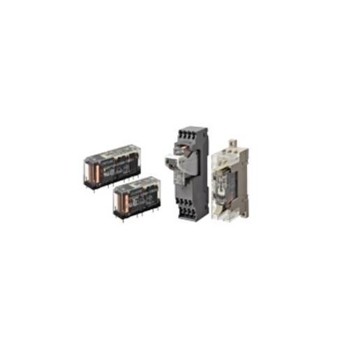
Compact, Slim Relays Conforming to EN Standards
G7SA Relays with Forcibly Guided Contacts OMRON
Ngan Anh Phat Co., Ltd specializes in providing genuine products G7SA Relays with Forcibly Guided Contacts from the manufacturer Omron, originating from Japan, to the Vietnamese market.
Outstanding features of the G7SA Relays with Forcibly Guided Contacts OMRON:
• Additional Push-In Plus terminal sockets are used to save wiring work in comparison with traditional screw terminals.
(Wiring time is reduced by 60%* in comparison with traditional screw terminals.)
• Relays with forcibly guided contacts (EN 61810-3, Certified by VDE).
• Supports the CE marking of machinery (Machinery Directive).
• Helps avoid hazardous machine status when used as part of an interlocking circuit.
• Four-pole and six-pole Relays are available.
• The Relay’s terminal arrangement simplifies PWB pattern design.
• Reinforced insulation between inputs and outputs. Reinforced insulation between some poles of different polarity.
* According to OMRON actual measurement data

Specifications
Safety Relay Unit
Coil (4 poles)
| Item | Rated current (mA) | Coil resistance (Ω) | Max. voltage (V) | Power consumption (mW) |
|---|---|---|---|---|
| Rated voltage | ||||
| 12 VDC | 30 | 400 | 110% | Approx. 360 |
| 18 VDC | 20 | 900 | ||
| 21 VDC | 17.1 | 1,225 | ||
| 24 VDC | 15 | 1,600 | ||
| 48 VDC | 7.5 | 6,400 | ||
| 110 VDC | 3.8 | 28,810 | Approx. 420 |
Coil (6 poles)
| Item | Rated current (mA) | Coil resistance (Ω) | Max. voltage (V) | Power consumption (mW) |
|---|---|---|---|---|
| Rated voltage | ||||
| 12 VDC | 41.7 | 288 | 110% | Approx. 500 |
| 18 VDC | 27.8 | 648 | ||
| 21 VDC | 23.8 | 882 | ||
| 24 VDC | 20.8 | 1,152 | ||
| 48 VDC | 10.4 | 4,606 | ||
| 110 VDC | 5.3 | 20,862 | Approx. 580 |
Note: 1. The rated current and coil resistance are measured at a coil temperature of 23°C with tolerances of ±15%.
2. The maximum voltage is based on an ambient operating temperature of 23°C maximum.
Contacts
| Load | Resistive load |
|---|---|
| Rated load | 6 A at 250 VAC, 6 A at 30 VDC |
| Rated carry current | 6 A |
| Max. switching voltage | 250 VAC, 125 VDC |
| Max. switching current | 6 A |
| Contact materials | Au plating + Ag alloy |
Characteristics
Safety Relay Unit
| Contact resistance *1 | 100 mΩ max. | |
|---|---|---|
| Operating time *2 | 20 ms max. | |
| Response time *3 | 10 ms max. | |
| Release time *2 | 20 ms max. | |
| Must operate voltage | 75% max. | |
| Must release voltage | 10% min. | |
| Maximum operating frequency |
Mechanical | 36,000 operations/h |
| Rated load | 1,800 operations/h | |
| Insulation resistance *4 | 1,000 MΩ min. | |
| Dielectric Strength *5 *6 |
Between coil and contacts |
4,000 VAC, 50/60 Hz for 1 min. |
| Between contacts of different olarity |
4,000 VAC, 50/60 Hz for 1 min. (except for followings) 4 poles (for poles 3-4 in 4-pole Relays), 6 poles (for poles 3-5, 4-6, and 5-6 in 6-pole Relays): 2,500 VAC, 50/60 Hz for 1 min. |
|
| Between contacts of the same polarity |
1,500 VAC, 50/60 Hz for 1 min. | |
| Vibration resistance | 10 to 55 to 10 Hz, 0.75-mm single amplitude (1.5-mm double amplitude) | |
| Shock resistance |
Destruction | 1,000 m/s2 |
| Malfunction | 100 m/s2 | |
| Durability *7 |
Mechanical | 10,000,000 operations min. (at approx. 36,000 operations/h) |
| Electrical | 100,000 operations min. (at the rated load) | |
| Inductive load switching capability *8 (IEC60947-5-1) |
AC15 240 VAC, 2 A DC13 24 VDC, 1 A/48 VDC, 0.5 A/110 VDC, 0.2 A |
|
| Failure rate (P level) (reference value *9) |
5 VDC, 1 mA | |
| Ambient operating temperature *10 |
12 to 48 VDC: -40 to 85°C (with no icing or condensation) 110 VDC: -40 to 60°C (with no icing or condensation) |
|
| Ambient operating humidity | 5% to 85% | |
| Weight | 4 poles: Approx. 22 g 6 poles: Approx. 25 g |
|
Note: 1. The above values are initial values.
2. Performance characteristics are based on coil temparature of 23°C.
*1. The contact resistance was measured with 1 A at 5 VDC using the voltage-drop method.
*2. These times were measured at the rated voltage and an ambient temperature of 23°C. Contact bounce time is not
included.
*3. The response time is the time it takes for the normally open contacts to open after the coil voltage is turned OFF.
Contact bounce time is included. Measurement conditions: Rated voltage operation, Ambient temperature: 23°C
*4. The insulation resistance was measured with a 500-VDC megohmmeter at the same locations as the dielectric
strength was measured.
*5. Pole 3 refers to terminals 31-32 or 33-34, pole 4 refers to terminals 43-44, pole 5 refers to terminals 53-54, and
pole 6 refers to terminals 63-64.
*6.When using a P7SA Socket, the dielectric strength between coil contacts/between contacts of different polarity is 2,500
VAC, 50/60 Hz for 1 min.
*7. The durability is for an ambient temperature of 15 to 35°C and an ambient humidity of 25% to 75%. For the durability
performance to the load, refer to the Durability Curve.
*8. AC15: cosφ = 0.3, DC13: L/R = 48-ms.
*9. The failure rate is based on an operating frequency of 300 operations/min.
*10. 12 to 48 VDC:
When operating between 70 and 85°C, reduce the rated carry current of 6 A by 0.1 A for each degree above 70°C.
(See Fig. 1.)
110 VDC:
When operating between 40 and 60°C, reduce the rated carry current of 6 A by 0.27 A for each degree above 40°C.
(See Fig. 1.)
Options (order separately)
Sockets
| Model | Push-In Plus terminals | Screw terminals | PCB terminals | ||||
|---|---|---|---|---|---|---|---|
| 4 poles | 6 poles | 4 poles | 6 poles | 4 poles | 6 poles | ||
| P7SA-10F-ND-PU | P7SA-14F-ND-PU | P7SA-10F(-ND) | P7SA-14F(-ND) | P7SA-10P | P7SA-14P | ||
| Ambient operating temperature | • With operation indicator LED/built-in diode P7SA-[]F-ND(-PU): -20 to +70°C • Without operation indicator LED/built-in diode P7SA-[]F: -40 to +85°C (with no icing or condensation) |
-40 to +85°C (with no icing or condensation) |
|||||
| Ambient operating humidity | 25% to 85% | 5% to 85% | |||||
| Continuous carry current | 6 A *1 | ||||||
| Dielectric strength |
Between coil and contact terminals |
4,000 VAC for 1 min. | 2,500 VAC for 1 min. | ||||
| Between contact terminals of different polarity |
2,500 VAC for 1 min. | ||||||
| Between contact terminals of same polarity |
1,500 VAC for 1 min. | ||||||
| Insulation resistance | 1,000 MΩ min. *2 | ||||||
| Weight | Approx. 58 g | Approx. 70 g | Approx. 44 g | Approx. 59 g | Approx. 9 g | Approx. 10 g | |
*1. When operating the P7SA-[]F-ND-PU at a temperature between 50 and 70°C, reduce the continuous current
(6 A at 50°C or less) by 0.25 A for each degree above 50°C.
When operating the P7SA-[]F-ND at a temperature between 50 and 70°C, reduce the continuous current
(6 A at 50°C or less) by 0.3 A for each degree above 50°C.
When operating the P7SA-[]F at a temperature between 50 and 85°C, reduce the continuous current
(6 A at 50°C or less) by 0.1 A for each degree above 50°C.
*2. Measurement conditions: For 500 VDC applied to the same location as for dielectric strength measurement.
Short Bars (for P7SA-[]F-ND-PU)
| Application | Applicable sockets |
Models | Maximum carry current |
Ambient operating temperature |
Ambient operating humidity |
|---|---|---|---|---|---|
| Crossover wiring of contact terminals (bottom) |
P7SA-[]F-ND-PU | XW5S-P2.5-2[] | 24 A | -40 to 55°C | 5% to 95% |
| XW5S-P2.5-3[] | |||||
| XW5S-P2.5-4[] | |||||
| XW5S-P2.5-5[] |
Certified Standards
Safety Relay Unit
EN Standards, VDE Certified
| Models | Ratings | Standard number | Certification No. | Operating coil | Contact ratings |
|---|---|---|---|---|---|
| G7SA-2A2B | 12, 18, 21, 24, 48, 110 VDC | EN/IEC 61810-1 Electromagnetic relay EN 61810-3 Relays with forcibly guided contacts |
125547 | 12, 18, 21, 24, 48, 110 VDC | 6 A, 240 VAC (Resistive) 6 A, 30 VDC (Resistive) |
| G7SA-3A1B | |||||
| G7SA-3A3B | |||||
| G7SA-4A2B | |||||
| G7SA-5A1B |
UL Standards Certification (File No. E41515) Industrial Control Devices
| Models | Category | Listed/Recognized | Contact ratings | Operating Coil ratings |
|---|---|---|---|---|
| G7SA-2A2B | E41515 | Recognized | 6 A, 250 VAC (Resistive) 6 A, 30 VDC (Resistive) |
12, 18, 21, 24, 48, 110 VDC |
| G7SA-3A1B | ||||
| G7SA-3A3B | ||||
| G7SA-4A2B | ||||
| G7SA-5A1B |
CSA standard CSA C22.2 No.14 Industrial Control Devices
| Models | Class number | File No. | Contact ratings | Operating Coil ratings |
|---|---|---|---|---|
| G7SA-2A2B | 3211-07 | LR35535 | 6 A, 250 VAC (Resistive) 6 A, 30 VDC (Resistive) |
12, 18, 21, 24, 48, 110 VDC |
| G7SA-3A1B | ||||
| G7SA-4A2B | ||||
| G7SA-5A1B |
South Korea S-mark certified (Rated voltage 24VDC only)
| Models | Applicable standard number |
|---|---|
| G7SA-2A2B DC24 | KS C IEC 61810-1 |
| G7SA-3A1B DC24 | |
| G7SA-3A3B DC24 | |
| G7SA-4A2B DC24 | |
| G7SA-5A1B DC24 |
CQC
| Models | Standard number | Certification No. |
|---|---|---|
| G7SA | GB/T, 21711.1 | CQC14002119869 |
Sockets
CE Marking Compliance
| Models | EMC Directive | Low Voltage Directive | Machinery Directive |
|---|---|---|---|
| P7SA (Excluding -P type) | Not applicable | Applicable | Not applicable |
| P7SA-PU | Not applicable | Applicable | Not applicable |
The CE compliance declaration was made in combination with the Safety Relay.
EN Standards, VDE Certified
| Models | Ratings | Standard number | Certification No. |
|---|---|---|---|
| P7SA | --- | EN61984 | 40007586 |
EN Standards, TÜV Certified
| Models | Ratings | Standard number | Certification No. |
|---|---|---|---|
| P7SA-PU | --- | EN61984 | R50356981 |
UL Standards Certification (File No. E87929) Industrial Control Devices
| Models | Category | Listed/Recognized |
|---|---|---|
| P7SA | SWIV2 | Recognized |
| P7SA-PU | SWIV2, SWIV8 | Recognized |
CSA standard CSA C22.2 No.14 Industrial Control Devices
| Models | Class number | File No. |
|---|---|---|
| P7SA | 3211-07, 3211-87 | LR35535 |
| P7SA-PU | 3211-07, 3211-87 | LR35535 |


- D3, Dong Khoi, Group 23, Quarter 35, Tam Hiep Ward, Dong Nai Province, Vietnam
- (+84) 2513 857 563
- info@ngananhphat.com, sales@ngananhphat.com
- www.ngananhphat.com

Giấy phép đăng ký kinh doanh số : 3600955737 do Sở Kế Hoạch & Đầu Tư Tỉnh Đồng Nai cấp ngày 19/11/2007.