
- AUTOMATION
- MACHINE DEVICE
- CONSTRUCT DEVICE
- FACTORY DEVICE
- TESTING DEVICE
- TENSION MEASUREMENT
- TRACTION MEASUREMENT
- TORQUE MEASUREMENT
- RPM MEASUREMENT
- THICKNESS MEASUREMENT
- STIFFNESS MEASUREMENT
- DISTANCE MEASUREMENT
- VISCOSITY MEASUREMENT
- FLOW/LEVEL MEASUREMENT
- DEPTH MEASUREMENT
- DIAL INDICATOR
- MICROMETER
- CALIPER
- MEASUREMENT ACCESSORIES
- MICROSCOPE
- MAGNIFIER
- TENSION TESTOR
- LINEAR SCALE
- TEMPERATURE MEASUREMENT
- WIND MEASUREMENT
- SOUND MEASUREMENT
- SPEED MEASUREMENT
- DENSITY MEASUREMENT
- CURRENT MEASUREMENT
- WEIGHT MEASUREMENT
- CALIPERS
- ENVICONMENT DEVICE
- SOLAR PRODUCTS
-
 AUTOMATION
CategoryBrand
AUTOMATION
CategoryBrand


-
 MACHINE DEVICE
-
 CONSTRUCT DEVICE
-
 FACTORY DEVICE
-
 TESTING DEVICE
Category
TESTING DEVICE
Category- TENSION MEASUREMENT
- TRACTION MEASUREMENT
- TORQUE MEASUREMENT
- RPM MEASUREMENT
- THICKNESS MEASUREMENT
- STIFFNESS MEASUREMENT
- DISTANCE MEASUREMENT
- VISCOSITY MEASUREMENT
- FLOW/LEVEL MEASUREMENT
- DEPTH MEASUREMENT
- DIAL INDICATOR
- MICROMETER
- CALIPER
- MEASUREMENT ACCESSORIES
- MICROSCOPE
- MAGNIFIER
- LINEAR SCALE
- TEMPERATURE MEASUREMENT
- WIND MEASUREMENT
- SOUND MEASUREMENT
- SPEED MEASUREMENT
- DENSITY MEASUREMENT
- CURRENT MEASUREMENT
- WEIGHT MEASUREMENT
Brand


-
 ENVICONMENT DEVICE
Brand
ENVICONMENT DEVICE
Brand


- Home Page
- Product
- AUTOMATION
- RELAY
- Power Relay G7J Omron

Power Relay G7J Omron
-
Product No4080
-
Brand
-
OriginJAPAN
-
Guarantee12 MONTHS
A High-capacity, High-dielectric-strength, Multi-pole Relay Used Like a Contactor

Power Relay G7J Omron
Ngan Anh Phat Co., Ltd specializes in providing genuine products Power Relay G7J from the manufacturer Omron, originating from Japan, to the Vietnamese market.
Outstanding features of the Power Relay G7J Omron:
• Miniature hinge for maximum switching power for motor loads as well as resistive and inductive loads.
• No contact chattering for momentary voltage drops up to 50% of rated voltage.
• Withstanding more than 4 kV between contacts that are different in polarity and between the coil and contacts.
• Flame-resistant materials (UL94V-0-qualifying) used for all insulation material.
• Standard models approved by UL and CSA.
Specifications
Coil Ratings
| Rated voltage | Rated current | Coil resistance | Must-operate voltage |
Must-release voltage |
Max. voltage | Power consumption |
|
|---|---|---|---|---|---|---|---|
| AC | 24 VAC | 75 mA | --- | 75% max. of rated voltage |
15% min. of rated voltage |
110% of rated voltage |
Approx. 1.8 to 2.6 VA |
| 50 VAC | 36 mA | --- | |||||
| 100 to 120 VAC | 18 to 21.6 mA | --- | |||||
| 200 to 240 VDC | 9 to 10.8 mA | --- | |||||
| DC | 12 VDC | 167 mA | 72 Ω | 10% min. of rated voltage |
Approx. 2.0 W | ||
| 24 VDC | 83 mA | 288 Ω | |||||
| 48 VDC | 42 mA | 1,150 Ω | |||||
| 100 VDC | 20 mA | 5,000 Ω | |||||
Note: 1. The rated current and coil resistance are measured at a coil temperature of 23°C with tolerances of +15%/-20%
for AC rated current and ±15% for DC coil resistance. (The values given for AC rated current apply at 50 Hz or
60 Hz.)
2. Performance characteristic data are measured at a coil temperature of 23°C.
3. The maximum voltage is one that is applicable to the Relay coil at 23°C.
Contact Ratings
| Item | Resistive load (cosφ = 1) | Inductive load (cosφ = 0.4) | Resistive load |
|---|---|---|---|
| Contact mechanism | Double break | ||
| Contact material | Ag alloy | ||
| Rated load | NO: 25 A at 220 VAC (1 A at 220 VAC) NC: 8 A at 220 VAC (1 A at 220 VAC) |
NO: 25 A at 30 VDC NC: 8 A at 30 VDC |
|
| Rated carry current | NO: 25 A (1 A) NC: 8 A (1 A) |
||
| Max. switching voltage | 250 VAC | 125 VDC | |
| Max. switching current | NO: 25 A (1 A) NC: 8 A (1 A) |
||
Note: The values in parentheses indicate values for a bifurcated contact.
Characteristics
| Contact resistance *2 | 100 mΩ max. |
|---|---|
| Operate time *3 | 50 ms max. |
| Release time *3 | 50 ms max. |
| Max. operating frequency | Mechanical: 1,800 operations/hr Electrical: 1,800 operations/hr |
| Insulation resistance *4 | 1,000 MΩ min. (at 500 VDC) |
| Dielectric strength | 4,000 VAC, 50/60 Hz for 1 min between coil and contacts 4,000 VAC, 50/60 Hz for 1 min between contacts of different polarity 2,000 VAC, 50/60 Hz for 1 min between contacts of same polarity |
| Impulse withstand voltage | 10,000 V between coil and contact (with 1.2 x 50 μs impulse wave) |
| Vibration resistance | Destruction: 10 to 55 to 10 Hz, 0.75-mm single amplitude (1.5-mm double amplitude) Malfunction: NO: 10 to 55 to 10 Hz, 0.75-mm single amplitude (1.5-mm double amplitude) NC: 10 to 26 to 10 Hz, 0.75-mm single amplitude (1.5-mm double amplitude) |
| Shock resistance | Destruction: 1,000 m/s2 Malfunction: NO: 100 m/s2, NC: 20 m/s2 |
| Endurance | Mechanical: 1,000,000 operations min. (at 1,800 operations/hr) Electrical: 100,000 operations min. (at 1,800 operations/hr) *5 |
| Error rate *6 | 100 mA at 24 VDC (bifurcated contact: 24 VDC 10 mA) |
| Ambient temperature | Operating: -25°C to 60°C (with no icing or condensation) |
| Ambient humidity | Operating: 5% to 85% |
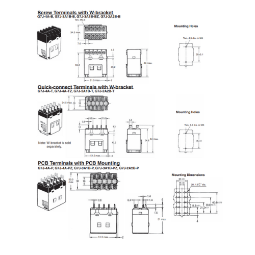
| Weight | PCB terminal: approx. 140 g Screw terminal: approx. 165 g Quick-connect terminal:approx. 140 g |
*1. The above values are all initial values.
*2. The contact resistance was measured with 1 A at 5 VDC using the voltage drop method.
*3. The operate and the release times were measured with the rated voltage imposed with any contact bounce ignored
at an ambient temperature of 23°C.
*4. The insulation resistance was measured with a 500-VDC megger applied to the same places as those used for
checking the dielectric strength.
*5. The electrical endurance was measured at an ambient temperature of 23°C.
*6. This value was measured at a switching frequency of 60 operations per minute.
Approved Standards
The G7J satisfies the following international standards. Approval for some international markings and symbols are still pending, however, and information on them will be added when they are approved.
UL (File No. E41643)
CSA (File No. LR35535)
| Coil ratings | Contact ratings | Number of test operations | |
|---|---|---|---|
| 24 to 265 VAC 6 to 110 VDC |
NO contact | 25 A 277 VAC, Resistive | 30,000 |
| 25 A 120 VAC, General Use | |||
| 25 A 277 VAC, General Use | |||
| 25 A 240 VAC, General Use | 100,000 | ||
| 1.5 kW 120 VAC, Tungsten | 6,000 | ||
| 1.5 hp 120 VAC | 1,000 | ||
| 3 hp 240/265/277 VAC | |||
| 3-phase 3 hp 240/265/277 VAC | 30,000 | ||
| 3-phase 5 hp 240/265/277 VAC | |||
| 20FLA/120LRA 120 VAC | |||
| 17FLA/102LRA 277 VAC | |||
| TV-10 120 VAC | 25,000 | ||
| 25 A 30 VDC, Resistive | 30,000 | ||
| *1 A 277 VAC, General Use | 6,000 | ||
| NC contact | 8 A 277 VAC, Resistive | 30,000 | |
| 8 A 120 VAC, General Use | |||
| 8 A 277 VAC, General Use | |||
| 8 A 30 VDC, Resistive | |||
| *1 A 277 VAC, General Use | 6,000 | ||
Note: *These ratings are bifurcated contact ratings.
Reference
UL approval: UL508 for industrial control devices
CSA approval: CSA C22.2 No. 14 for industrial control devices
VDE (File No. 5381UG)
| Model | Contact ratings | |
|---|---|---|
| NO contact | NC contact | |
| G7J-4A-B(P) (T)-KM G7J-2A2B(P) (T)-KM G7J-3A1B-B(P) (T)-KM |
25 A 240 VAC cosφ = 0.4 25 A 240 VAC cosφ = 1 25 A 30 VDC L/R ≥ 1 |
8 A 240 VAC cosφ = 0.4 8 A 240 VAC cosφ = 1 8 A 30 VDC L/R ≥ 1 |
Note: Ask your OMRON representative for details on specifications.
Reference
VDE approval: EN60255-1-00: 1997
EN60255-23: 1996
KEMA (File No. 2001291.02)
| Model | Contact ratings |
|---|---|
| NO contact | |
| G7J-4A-B(P) (T) (Z)-KM G7J-2A2B(P) (T)-KM |
Class AC1: 25 A at 220 VAC 11.5 A at 380 to 480 VAC Class AC3: 11.5 A at 220 VAC and 8.5 A at 380 to 480 VAC *Class AC1: 1 A at 220 VAC |
| G7J-3A1B-B(P) (T) (Z)-KM |
Note: Ask your OMRON representative for details on specifications.
*This rating is the bifurcated contact rating.
Reference
KEMA approval: EN60947-4-1 for contacts


- D3, Dong Khoi, Group 23, Quarter 35, Tam Hiep Ward, Dong Nai Province, Vietnam
- (+84) 2513 857 563
- info@ngananhphat.com, sales@ngananhphat.com
- www.ngananhphat.com

Giấy phép đăng ký kinh doanh số : 3600955737 do Sở Kế Hoạch & Đầu Tư Tỉnh Đồng Nai cấp ngày 19/11/2007.
