


Motor Protection Circuit Breaker J7MN OMRON
-
Product No4097
-
Brand
-
OriginJAPAN
-
Guarantee12 MONTHS
MPCB system (motor protection CLASS 10)

Motor Protection Circuit Breaker J7MN OMRON
Ngan Anh Phat Co., Ltd specializes in providing genuine products Motor Protection Circuit Breaker J7MN OMRON from the manufacturer Omron, originating from Japan, to the Vietnamese market.
Outstanding features of the Cables for Motor Protection Circuit Breaker J7MN OMRON
MPCB system (motor protection CLASS 10)
• Rotary and switch types
• Rated operational current = 12 A, 25 A, 50 A and 100 A
• Switching capacity up to 12.5 A = 100 kA/400 V
• Fixed short-circuit release = 13 x Iu
• Overload release adjustable 0.7 - 1 x Iu
• Single phasing sensivity
Auxiliary contact modules
• ON/OFF indication for MPCB front mounting and side mounting
• Trip indication for MPCB side mounting
Accessories
• Undervoltage release
• Shunt release
• Three phase busbar system up to 5 MPCB
• Moulded plastic enclosures (IP55)
• Moulded plastic front plates (IP55)
• Door coupling rotary mechanisms (black and red/yellow)
Specifications
Components for Fuseless Load Feeders, DIN-Rail Mounting
Type of coordination „1“ 3 x 415 V 10 kA (other conditions on request)
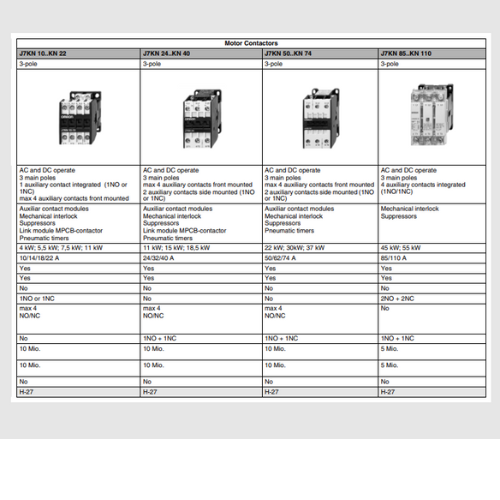
| Motor 3~400V kW |
Setting range A |
Circuit-breaker Type |
Contactor 220-230V 50Hz Type |
Link module Type |
DIN-rail adapter Type |
|---|---|---|---|---|---|
| - | 0.11 - 0.16 | J7MN-25-E16 | J7KN-10-10 230 | J74MN-VD-12 | J74MN-HU |
| - | 0.14 - 0.2 | J7MN-25-E2 | J7KN-10-10 230 | J74MN-VD-12 | J74MN-HU |
| 0.06 | 0.18 - 0.25 | J7MN-25-E25 | J7KN-10-10 230 | J74MN-VD-12 | J74MN-HU |
| 0.09 | 0.22 - 0.32 | J7MN-25-E32 | J7KN-10-10 230 | J74MN-VD-12 | J74MN-HU |
| - | 0.28 - 0.4 | J7MN-25-E4 | J7KN-10-10 230 | J74MN-VD-12 | J74MN-HU |
| 0.12 | 0.35 - 0.5 | J7MN-25-E5 | J7KN-10-10 230 | J74MN-VD-12 | J74MN-HU |
| 0.18 | 0.45 - 0.63 | J7MN-25-E63 | J7KN-10-10 230 | J74MN-VD-12 | J74MN-HU |
| - | 0.55 - 0.8 | J7MN-25-E8 | J7KN-10-10 230 | J74MN-VD-12 | J74MN-HU |
| 0.25 | 0.7 - 1 | J7MN-25-1 | J7KN-10-10 230 | J74MN-VD-12 | J74MN-HU |
| 0.37 | 0.9 - 1.25 | J7MN-25-1E25 | J7KN-10-10 230 | J74MN-VD-12 | J74MN-HU |
| 0.55 | 1.1 - 1.6 | J7MN-25-1E6 | J7KN-10-10 230 | J74MN-VD-12 | J74MN-HU |
| 0.75 | 1.4 - 2 | J7MN-25-2 | J7KN-10-10 230 | J74MN-VD-12 | J74MN-HU |
| - | 1.8 - 2.5 | J7MN-25-2E5 | J7KN-10-10 230 | J74MN-VD-12 | J74MN-HU |
| 1.1 | 2.2 - 3.2 | J7MN-25-3E2 | J7KN-10-10 230 | J74MN-VD-12 | J74MN-HU |
| 1.5 | 2.8 - 4 | J7MN-25-4 | J7KN-10-10 230 | J74MN-VD-12 | J74MN-HU |
| - | 3.5 - 5 | J7MN-25-5 | J7KN-10-10 230 | J74MN-VD-12 | J74MN-HU |
| 2.2 | 4.5 - 6.3 | J7MN-25-6E3 | J7KN-10-10 230 | J74MN-VD-12 | J74MN-HU |
| 3 | 5.5 - 8 | J7MN-25-8 | J7KN-10-10 230 | J74MN-VD-12 | J74MN-HU |
| 4 | 7 - 10 | J7MN-25-10 | J7KN-10-10 230 | J74MN-VD-12 | J74MN-HU |
| 5.5 | 9 - 12.5 | J7MN-25-12E5 | J7KN-14-10 230 | J74MN-VD-12 | J74MN-HU |
| 7.5 | 11 - 16 | J7MN-25-16 | J7KN-18-10 230 | J74MN-VD-12 | J74MN-HU |
| - | 14 - 20 | J7MN-25-20 | J7KN-22-10 230 | J74MN-VD-25 | J74MN-HU |
| - | 17 - 22 | J7MN-25-22 | J7KN-22-10 230 | J74MN-VD-25 | J74MN-HU |
| 11 | 20 - 25 | J7MN-25-25 | J7KN-22-10 230 | J74MN-VD-25 | J74MN-HU |
Technical Data according to IEC/EN 60947-1, 60947-2, 60947-4-1 and VDE 0660
This table shows the rated ultimate short-circuit breaking capacity Icu and the rated service short-circuit breaking capacity Ics of the J7MN circuit-breakers with different operational voltages as a function of the rated current In of the circuit-breakers.
The circuit-breakers can be fed at the top or bottom supply terminals without any reduction of the rated data.
If the short-circuit current exceeds the rated short-circuit breaking capacity of the circuit-breaker specified in the tables at the installation point, a back-up fuse is to be used.
The maximum rated current for the back-up fuse is specified in the tables. These fuses are only suitable for the short-circuit-currents as indicated on the fuses.
| Circuit- breaker Type |
Rated current In A |
up to AC 240V *1 | up to AC 400V *1 up to AC 415V *2 |
up to AC 440V *1 up to AC 460V *2 |
||||||
|---|---|---|---|---|---|---|---|---|---|---|
| Icu kA |
Ics kA |
max. fuse (gL/gG) A |
Icu kA |
Ics kA |
max. fuse (gL/gG) A |
Icu kA |
Ics kA |
max. fuse (gL/gG) A |
||
| J7MN-12 | 0.16 to 0.8 | 100 | 100 | -- | 100 | 100 | -- | 100 | 100 | -- |
| 1 | 100 | 100 | -- | 100 | 100 | -- | 100 | 100 | -- | |
| 1.25 | 100 | 100 | -- | 100 | 100 | -- | 100 | 100 | -- | |
| 1.6 | 100 | 100 | -- | 100 | 100 | -- | 100 | 100 | -- | |
| 2 | 100 | 100 | -- | 100 | 100 | -- | 100 | 100 | -- | |
| 2.5 | 100 | 100 | -- | 100 | 100 | -- | 100 | 100 | -- | |
| 3.2 | 100 | 100 | -- | 100 | 100 | -- | 10 | 10 | 40 | |
| 4 | 100 | 100 | -- | 100 | 100 | -- | 10 | 10 | 40 | |
| 5 | 100 | 100 | -- | 100 | 100 | -- | 10 | 10 | 50 | |
| 6.3 | 100 | 100 | -- | 100 | 100 | -- | 10 | 10 | 50 | |
| 8 | 100 | 100 | -- | 50 | 12.5 | 80 *3 | 10 | 10 | 63 | |
| 10 | 100 | 100 | -- | 50 | 12.5 | 80 *3 | 10 | 10 | 63 | |
| 12 | 100 | 100 | -- | 50 | 12.5 | 80 *3 | 10 | 10 | 80 | |
| J7MN-25 | 0.16 to 1.25 | 100 | 100 | -- | 100 | 100 | -- | 100 | 100 | -- |
| 1.6 | 100 | 100 | -- | 100 | 100 | -- | 100 | 100 | -- | |
| 2 | 100 | 100 | -- | 100 | 100 | -- | 100 | 100 | -- | |
| 2.5 | 100 | 100 | -- | 100 | 100 | -- | 100 | 100 | -- | |
| 3.2 | 100 | 100 | -- | 100 | 100 | -- | 100 | 100 | -- | |
| 4 | 100 | 100 | -- | 100 | 100 | -- | 100 | 100 | -- | |
| 5 | 100 | 100 | -- | 100 | 100 | -- | 100 | 100 | -- | |
| 6.3 | 100 | 100 | -- | 100 | 100 | -- | 100 | 100 | -- | |
| 8 | 100 | 100 | -- | 100 | 100 | -- | 50 | 25 | 63 *3 | |
| 10 | 100 | 100 | -- | 100 | 100 | -- | 50 | 25 | 80 *3 | |
| 12.5 | 100 | 100 | -- | 100 | 100 | -- | 50 | 25 | 80 *3 | |
| 16 | 100 | 100 | -- | 50 | 25 | 100 *3 | 20 | 10 | 80 | |
| 20 | 100 | 100 | -- | 50 | 25 | 125 *3 | 20 | 10 | 80 | |
| 22 | 100 | 100 | -- | 50 | 25 | 125 *3 | 20 | 10 | 100 | |
| 25 | 100 | 100 | -- | 50 | 25 | 125 *3 | 20 | 10 | 100 | |
| J7MN-50 | 25 | 100 | 100 | -- | 50 | 25 | 125 *3 | 30 | 15 | 100 |
| 32 | 100 | 100 | -- | 50 | 25 | 125 *3 | 30 | 15 | 125 | |
| 40 | 100 | 100 | -- | 50 | 25 | 160 *3 | 30 | 15 | 125 | |
| 45 | 100 | 100 | -- | 50 | 25 | 160 *3 | 30 | 15 | 125 | |
| 50 | 100 | 100 | -- | 50 | 25 | 160 *3 | 30 | 15 | 125 | |
| J7MN-100 | 63 | 100 | 100 | -- | 50 | 25 | 160 *3 | 40 | 20 | 160 |
| 75 | 100 | 100 | -- | 50 | 25 | 160 *3 | 40 | 20 | 160 | |
| 90 | 100 | 100 | -- | 50 | 25 | 160 *3 | 40 | 20 | 160 | |
| 100 | 100 | 100 | -- | 50 | 25 | 160 *3 | 40 | 20 | 160 | |
| Circuit- breaker Type |
Rated current In A |
up to AC 500V *1 up to AC 525V *2 |
up to AC 690V *1 | ||||
|---|---|---|---|---|---|---|---|
| Icu kA |
Ics kA |
max. fuse (gL/gG) A |
Icu kA |
Ics kA |
max. fuse (gL/gG) A |
||
| J7MN-12 | 0.16 to 0.8 | 100 | 100 | -- | 100 | 100 | -- |
| 1 | 100 | 100 | -- | 100 | 100 | -- | |
| 1.25 | 100 | 100 | -- | 2 | 2 | 20 | |
| 1.6 | 100 | 100 | -- | 2 | 2 | 20 | |
| 2 | 10 | 10 | 35 | 2 | 2 | 35 | |
| 2.5 | 10 | 10 | 35 | 2 | 2 | 35 | |
| 3.2 | 3 | 3 | 40 | 2 | 2 | 40 | |
| 4 | 3 | 3 | 40 | 2 | 2 | 40 | |
| 5 | 3 | 3 | 50 | 2 | 2 | 50 | |
| 6.3 | 3 | 3 | 50 | 2 | 2 | 50 | |
| 8 | 3 | 3 | 63 | 2 | 2 | 63 | |
| 10 | 3 | 3 | 63 | 2 | 2 | 63 | |
| 12 | 3 | 3 | 80 | 2 | 2 | 80 | |
| J7MN-25 | 0.16 to 1.25 | 100 | 100 | -- | 100 | 100 | -- |
| 1.6 | 100 | 100 | -- | 100 | 100 | -- | |
| 2 | 100 | 100 | -- | 8 | 8 | 25 | |
| 2.5 | 100 | 100 | -- | 8 | 8 | 25 | |
| 3.2 | 100 | 100 | -- | 8 | 8 | 32 | |
| 4 | 100 | 100 | -- | 6 | 3 | 32 | |
| 5 | 100 | 100 | -- | 6 | 3 | 32 | |
| 6.3 | 100 | 100 | -- | 6 | 3 | 50 | |
| 8 | 42 | 21 | 63 | 6 | 3 | 50 | |
| 10 | 42 | 21 | 63 | 6 | 3 | 50 | |
| 12.5 | 42 | 21 | 80 | 6 | 3 | 63 | |
| 16 | 10 | 5 | 80 | 4 | 2 | 63 | |
| 20 | 10 | 5 | 80 | 4 | 2 | 63 | |
| 22 | 10 | 5 | 80 | 4 | 2 | 63 | |
| 25 | 10 | 5 | 80 | 4 | 2 | 63 | |
| J7MN-50 | 25 | 12 | 6 | 80 | 5 | 3 | 63 |
| 32 | 10 | 5 | 100 | 4 | 2 | 63 | |
| 40 | 10 | 5 | 100 | 4 | 2 | 63 | |
| 45 | 10 | 5 | 100 | 4 | 2 | 63 | |
| 50 | 10 | 5 | 100 | 4 | 2 | 80 | |
| J7MN-100 | 63 | 12 | 6 | 125 | 6 | 3 | 80 |
| 75 | 8 | 4 | 125 | 5 | 3 | 100 | |
| 90 | 8 | 4 | 125 | 5 | 3 | 125 | |
| 100 | 8 | 4 | 125 | 5 | 3 | 125 | |
*1. 10% overvoltage
*2. 5% overvoltage
*3. Back-up fuse required if short-circuit current at installation point > 50 kA
-- No back-up fuse required.
Main Circuit
| Type | J7MN-12 | J7MN-25 | J7MN-50 | J7MN-100 | |||
|---|---|---|---|---|---|---|---|
| Number of poles | 3 | 3 | 3 | 3 | |||
| Max. rated current Inmax (=max. rated operational current Ie) |
A | 12 | 25 | 50 | 100 | ||
| Permissible ambient temperature |
Storage/transport | °C | -50 to +80 | ||||
| Operation | °C | -20 to +70 *1 | |||||
| Permissible rated current at temperature inside cubicle of: |
+60 °C | % | 100 | ||||
| +70 °C | % | 87 | |||||
| Circuit-breaker inside enclosure Permissible rated current at temperature inside enclosure of: |
+60 °C | % | 100 | ||||
| +70 °C | % | 87 | |||||
| Rated operational voltage Ue | V | 690 *2 | |||||
| Rated frequency | Hz | 50/60 | |||||
| Rated insulation voltage Ui | V | 690 | |||||
| Rated impulse withstand voltage Uimp | kV | 6 | |||||
| Utilization category | IEC 60 947-2 (circuit-breaker) | A | |||||
| IEC 60 947-4-1 (motor starter) | AC-3 | ||||||
| Class | acc. to IEC 60 947-4-1 | 10 | |||||
| DC short-circuit breaking capacity (time constant t = 5 ms) |
1 conducting path DC 150 V | kA | 10 | ||||
| 2 conducting paths in series DC 300 V |
kA | 10 | |||||
| 3 conducting paths in series DC 450 V |
kA | 10 | |||||
| Power loss Pv per circuit-breaker dependent on rated current In (upper setting range) R per conducting path = P/(I2 × 3) |
In -> to 1.25 A In -> 1.6 to 6.3 A In -> 8 to 12 A |
W W W |
5 6 7 |
- - - |
- - - |
- - - |
|
| In -> 1 to 6.3 A In -> 8 to 16 A In -> 20 to 25 A |
W W W |
- - - |
6 7 8 |
- - - |
- - - |
||
| In -> to 25 A In -> 32 A In -> 40 to 50 A |
W W W |
- - - |
- - - |
12 15 20 |
- - - |
||
| In -> to 63 A In -> 75 to 90 A In -> to 100 A |
W W W |
- - - |
- - - |
- - - |
20 30 38 |
||
| Shock resistance | acc. to IEC 68 Part 2-27 | g | 25 | 25 | 25 | 25 | |
| Degree of protection | acc. to IEC 60 529 | IP 20 | IP 20 | IP 20 *3 | IP 20 *3 | ||
| Shock hazard protection |
acc. to DIN VDE 0106 Part 100 | safe against finger touch | |||||
| Temperature compensation |
acc. to IEC 60 947-4-1 | °C | -20 to +60 | ||||
| Phase failure sensitivity |
acc. to IEC 60 947-4-1 | yes | |||||
| Explosion protection | acc. to EC Directive 94191 EC | yes *4 | |||||
| Isolator characteristics |
acc. to IEC 60 947-3 | yes | |||||
| Main and EM. STOP switch characteristics |
acc. to IEC 60 204-1 (VDE 0113) | yes *5 | |||||
| Safe isolation between main and auxiliary circuits |
acc. to DIN VDE 0106 Part 101 |
up to 400 V +10 % |
yes | ||||
| up to 415 V +5 % |
yes | ||||||
| Mechanical endurance | operating cycles | 100 000 | 100 000 | 50 000 | 50 000 | ||
| Electrical endurance | 100 000 | 100 000 | 25 000 | 25 000 | |||
| Max. operating frequency per hour (motor starts) | 1/h | 15 | 15 | 15 | 15 | ||
| Permissible mounting position | any. acc. to IEC 60 447 start command "I" right- hand side or top |
||||||
*1. Over +60°C current reduction
*2. 500 V with moulded-plastic enclosure
*3. Terminal compartment IP00
*4. KEMA-test certification on request
*5. With appropriate accessories
Conductor cross-sections for main Circuit
| Type | J7MN-12 | J7MN-25 | J7MN-50 | J7MN-100 | ||
|---|---|---|---|---|---|---|
| Terminal type | Screw-type | Screw-type | Box terminal | Box terminal | ||
| Terminal screw | Pozidriv size 2 | Pozidriv size 2 | Pozidriv size 2 | Allen screw 4 mm | ||
| Tightening torque | Nm | 0.8 to 1.2 | 2 to 2.5 | 3 to 4.5 | 4 to 6 | |
| Conductor cross- sections |
solid | mm2 | 2 x (0.5 to 1.5) | 2 x (1 to 2.5) | 2 x (0.75 to 16) | 2 x (2.5 to 16) |
| mm2 | 2 x (0.75 to 2.5) | 2 x (2.5 to 6) | - | - | ||
| mm2 | 1 x (0.5 to 4) | |||||
| finely stranded with end ferrule |
mm2 | 2 x (0.5 to 1.5) | 2 x (1 to 2.5) | 2 x (0.75 to 16) | 2 x (2.5 to 35) | |
| mm2 | 2 x (0.75 to 2.5) | 2 x (2.5 to 6) | 1 x (0.75 to 25) | 1 x (2.5 to 50) | ||
| mm2 | 1 x (1 to 10) | |||||
| stranded | mm2 | 2 x (0.5 to 1.5) | 2 x (1 to 2.5) | 2 x (0.75 to 25) | 2 x (10 to 50) | |
| mm2 | 2 x (0.75 to 2.5) | 2 x (2.5 to 6) | 1 x (0.75 to 35) | 1 x (10 to 70) | ||
| mm2 | 1 x (0.5 to 4) | 1 x (1 to 10) | ||||
| AWG-wires, solid or stranded |
AWG | 2 x (18 to 14) | 2 x (14 to 10) | 2 x (18 to 3) | 2 x (10 to 1/0) | |
| AWG | - | - | 1 x (18 to 2) | 1 x (10 to 2/0) | ||
| conductor bar (number x width x thick) |
mm | - | - | 2 x (6 x 9 x 0.8) | 2 x (6 x 9 x 0.8) | |
| mm | - | - | - | 18 x 10 | ||
| mm2 | - | - | - | up to 2 x 70 | ||
Auxiliary switches
| Switching capacity | Control voltage | ||||||
|---|---|---|---|---|---|---|---|
| Front transverse auxiliary switch with 1 NO + 1 NC |
Rated operational voltage Ue |
AC | V | 24 | 230 | ||
| Rated operational current Ie/AC-15 |
A | 2 | 0.5 | ||||
| Rated operational current Ie/AC-12 Ith |
A | 2.5 | 2.5 | ||||
| Rated operational voltage Ue |
DC L/R 200 ms |
V | 24 | 48 | 60 | ||
| Rated operational current Ie/DC-13 |
A | 1 | 0.3 | 0.15 | |||
| Lateral auxiliary switch and signalling switch |
Rated operational voltage Ue |
AC | V | 24 | 230 | 400 | 690 |
| Rated operational current Ie/AC-15 |
A | 6 | 6 | 3 | 1 | ||
| Rated operational current Ie/AC-12 Ith |
A | 10 | 10 | 10 | 10 | ||
| Rated operational voltage Ue |
DC L/R 200 ms |
V | 24 | 110 | 220 | 440 | |
| Rated operational current Ie/DC-13 |
A | 2 | 0.5 | 0.25 | 0.1 | ||
| Undervoltage release |
Power consumption | during pick-up | VA/W | 20.2/13 | |||
| uninter-rupted duty |
VA/W | 7.2/2.4 | |||||
| Response voltage | trip | V | 0.7 to 0.35 × Us | ||||
| pick-up | V | 0.85 to 1.1 × Us | |||||
| Max. opening time | ms | 20 | |||||
| Shunt release | Power consumption during pick-up | AC VA/W | 20.2/13 | ||||
| DC W | 13 to 80 | ||||||
| Response voltage acc. to IEC 60 947-1, trip |
V | 0.7 to 1.1 × Us | |||||
| Max. opening time | ms | 20 | |||||
| Short-circuit protection for auxiliary and control circuits |
Fuse | gL/gG | A | 10 | |||
| Miniature circuit breaker C- characteristic |
A | 6 *1 | |||||
| Conductor cross-sections for auxiliary and control circuits |
Screw-type Pozidriv size 2 | ||||||
| solid | mm2 | 2 x (0.5 to 1.5)/2 x (0.75 to 2.5) | |||||
| finely stranded with ferrule | mm2 | 2 x (0.5 to 1.5)/2 x (0.75 to 2.5) | |||||
| stranded | mm2 | 2 x (0.5 to 1.5)/2 x (0.75 to 2.5) | |||||
| AWG-wires, solid or stranded | AWG | 2 x (18 to 14) | |||||
*1.Prospective short-circuit current < 0.4 kA.


- D3, Dong Khoi, Group 23, Quarter 35, Tam Hiep Ward, Dong Nai Province, Vietnam
- (+84) 2513 857 563
- info@ngananhphat.com, sales@ngananhphat.com
- www.ngananhphat.com

Giấy phép đăng ký kinh doanh số : 3600955737 do Sở Kế Hoạch & Đầu Tư Tỉnh Đồng Nai cấp ngày 19/11/2007.