


MMK Latching Relay OMRON
-
Product No3972
-
Brand
-
OriginJAPAN
-
Guarantee12 MONTHS
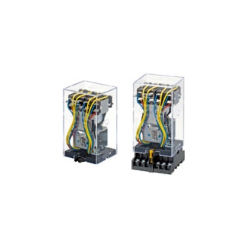
Mechanically Latching Relays Based on the MM Power Relay

MMK Latching Relay OMRON
Ngan Anh Phat Co., Ltd specializes in providing genuine products MMK Latching Relay from the manufacturer Omron, originating from Japan, to the Vietnamese market.
Outstanding features of the MMK Latching Relay OMRON:
-
Tiêu thụ điện năng thấp nhờ vào cơ chế giữ cơ học cho hoạt động kinh tế.
-
Có thể sản xuất rơle với các thông số cuộn dây hỗn hợp (ví dụ: cuộn dây đặt AC và cuộn dây đặt lại DC).
-
Phản ứng hoạt động đủ nhanh để cho phép ứng dụng nguồn tín hiệu xung.
-
Nhiệt độ hoạt động môi trường: -10°C đến 55°C.
Thông số kỹ thuật
Coil Ratings
Set Coil
| Rated voltage (V) |
Rated current (mA) | Coil resistance (Ω) |
Set volt. |
Max volt. |
Power con- sump- tion (VA or W) |
|||||||||
|---|---|---|---|---|---|---|---|---|---|---|---|---|---|---|
| DP | 3P, 4P | DP | 3P, 4P |
|||||||||||
| Open Relays |
Cased | Open Relays |
Cased | Open Relays |
Cased | Open Relays |
Cased | |||||||
| 50 Hz | 60 Hz | 50 Hz | 60 Hz | 50 Hz | 60 Hz | 50 Hz | 60 Hz | % of rated voltage |
||||||
| AC | 6 | 790 | 655 | 690 | 590 | 1,285 | 1,100 | 1,165 | 1,000 | 1.1 | 0.46 | 80% max. |
110 % |
Initial: DP: Approx. 6.2 3P, 4P: Approx. 12 Rated: DP: Approx. 3.5 (3.9) 3P, 4P: Approx. 6 (6.6) * |
| 12 | 395 | 325 | 345 | 295 | 640 | 550 | 580 | 500 | 4.7 | 1.9 | ||||
| 24 | 195 | 160 | 170 | 145 | 320 | 275 | 290 | 250 | 19 | 8.2 | ||||
| 100/ (110) |
47 | 39/45 | 41 | 35/40 | 77 | 66/76 | 70 | 60/68 | 340 | 141 | ||||
| 200/ (220) |
23.5 | 19.5/ 22.5 |
20.5 | 17.5/ 20 |
38.5 | 33/38 | 35 | 30/34 | 1,540 | 563 | ||||
| DC | 6 | 340 | 450 | 17.5 | 13.4 | DP: Approx. 2.1 3P, 4P: Approx. 2.7 |
||||||||
| 12 | 176 | 220 | 68 | 54 | ||||||||||
| 24 | 87 | 94 | 275 | 255 | ||||||||||
| 48 | 41 | 52 | 1,180 | 930 | ||||||||||
| 100/ 110 |
17/19 | 22/24.5 | 5,750 | 4,500 | ||||||||||
| 125 | 17 | 22 | 7,430 | 5,800 | ||||||||||
| 200/ 220 |
8.6/9.5 | 11/12 | 23,200 | 18,000 | ||||||||||
Note: 1. The rated current and coil resistance are measured at a coil temperature of 23°C with tolerances of +15%/-20%
for AC rated current and ±15% for DC coil resistance.
2. Performance characteristic data are measured at a coil temperature of 23°C.
3. The AC coil resistance values are reference values.
4. The maximum voltage is one that is applicable instantaneously to the Relay coil at an ambient temperature of
23°C and not continuously.
* Values in parentheses are for open relays.
Reset Coil
| Rated voltage (V) |
Rated current (mA) | Coil resistance (Ω) |
Reset voltage | Maximum voltage | Power consumption (VA or W) |
||
|---|---|---|---|---|---|---|---|
| 50 Hz | 60 Hz | % of rated voltage | |||||
| AC | 6 | 770 | 690 | 2.3 | 80% max. | 110% | Initial: Approx. 6.5 Rated: Approx. 4.1 |
| 12 | 385 | 345 | 9.2 | ||||
| 24 | 191 | 170 | 35 | ||||
| 100/(110) | 46 | 41/46 | 739 | ||||
| 200/(220) | 23 | 20/23 | 3,030 | ||||
| DC | 6 | 422 | 14.2 | Approx. 2.8 | |||
| 12 | 215 | 56 | |||||
| 24 | 109 | 220 | |||||
| 48 | 58 | 832 | |||||
| 100/110 | 25/27 | 4,040 | |||||
| 125 | 23.5 | 5,330 | |||||
| 200/220 | 12.2/13.5 | 16,330 | |||||
Note: 1. The rated current and coil resistance are measured at a coil temperature of 23°C with tolerances of +15%/-20%
for AC rated current and ±15% for DC coil resistance.
2. Performance characteristic data are measured at a coil temperature of 23°C.
3. The AC coil resistance values are reference values.
4. The maximum voltage is one that is applicable instantaneously to the Relay coil at an ambient temperature of
23°C and not continuously.
Coils (Conforming to Auxiliary Power Relay Specifications)
| Rated voltage (V) |
Rated current (mA) |
Coil resistance (Ω) |
Set volt- age |
Reset volt- age |
Max. volt- age |
Op- era- tion level (JEC- 174D) |
Power consumption (VA or W) |
||||||||
|---|---|---|---|---|---|---|---|---|---|---|---|---|---|---|---|
| Set coil |
Reset coil |
Set coil |
Reset coil |
Set coil | Reset coil | ||||||||||
| 50 Hz |
60 Hz |
50 Hz |
60 Hz |
% of rated voltage | Initial | Rated | Initial | Rated | |||||||
| AC | 24 | 245 | 210 | 191 | 170 | 8.5 | 35 | 80% max. |
80% max. |
110% | A | Approx. 6.3 |
Approx. 5.1 |
Approx. 6.5 |
Approx. 4.1 |
| 100/ (110) |
58.5 | 51/ 58 |
46 | 41/ 46 |
150 | 739 | |||||||||
| 110 | 53 | 46 | 42 | 37.3 | 182 | 835 | |||||||||
| 115 | 51 | 44 | 40 | 35.7 | 210 | 885 | |||||||||
| 200/ (220) |
29 | 25.5 /29 |
23 | 20.5 /23 |
620 | 3,030 | |||||||||
| 220 | 26.5 | 23 | 21 | 18.6 | 780 | 3,420 | |||||||||
| DC | 24 | 94 | 109 | 255 | 220 | Approx. 2.7 | Approx. 2.8 | ||||||||
| 48 | 52 | 58 | 930 | 832 | |||||||||||
| 100/ 110 |
22/24.5 | 25/27 | 4,500 | 4,040 | |||||||||||
| 125 | 22 | 23.5 | 5,800 | 5,330 | |||||||||||
| 200/ 220 |
11/12 | 12.2/13.5 | 18,000 | 16,330 | |||||||||||
Note: 1. The rated current and coil resistance are measured at a coil temperature of 23°C with tolerances of +15%/-20%
for AC rated current and ±15% for DC coil resistance.
2. The AC coil resistance and coil inductance values are for reference only.
3. Performance characteristic data are measured at a coil temperature of 23°C.
4. The maximum voltage is one that is applicable instantaneously to the Relay coil at an ambient temperature of
23°C and not continuously.
Contact Ratings
Standard Relays
| Item | Open Relays: MM2K(B), MM3K(B), MM4K(B) |
Cased Relays: MM2KP, MM3KP, MM4KP |
||
|---|---|---|---|---|
| Resistive load (cosφ = 1) |
Inductive load (cosφ=0.4, L/R=7 ms) |
Resistive load (cosφ = 1) |
Inductive load (cosφ=0.4, L/R=7 ms) |
|
| Contact mechanism | Single | |||
| Contact material | Ag | |||
| Rated load | 10 A at 220 VAC 7 A at 24 VDC |
5 A at 220 VAC 4 A at 24 VDC |
||
| Rated carry current | 10 A | 5 A | ||
| Max. switching voltage | 250 VAC, 250 VDC | 250 VAC, 250 VDC | ||
| Max. switching current | 10 A | 5 A | ||
| Max. switching power (reference value) |
2,200 VA, 168 W | 1,100 VA, 96W | ||
DC-switching Relays
| Item | Open Relays: MM2XK(B), MM3XK(B), MM4XK(B) |
Cased Relays: MM2XKP, MM3XKP, MM4XKP |
||
|---|---|---|---|---|
| Resistive load (cosφ = 1) |
Inductive load (cosφ=0.4, L/R=7 ms) |
Resistive load (cosφ = 1) |
Inductive load (cosφ=0.4, L/R=7 ms) |
|
| Contact mechanism | Single | |||
| Contact material | Ag | |||
| Rated load | 7 A at 110 VDC | 6 A at 110 VDC | 5 A at 110 VDC | |
| Rated current flow | 10 A | 5 A | ||
| Max. switching voltage | 250 VAC, 250 VDC | 250 VAC, 250 VDC | ||
| Max. switching current | 10 A | 5 A | ||
| Max. switching power (reference value) |
800 W, 20 VA *1 | 660 W, 20 VA *1 | 700 W, 20 VA *1 | 600 W, 20 VA *1 |
Note: 1. When switching DC inductive loads at 125 V or more, an unstable region exists for a switching current of between
0.5 and 2.5 A. The Relay will not turn OFF in this region. Use a switching current of 0.5 A or less when switching
125 VDC or more.
2. If L/R exceeds 7 ms when switching DC inductive loads, an arc-breaking time of up to 50 ms must be considered
in application and the circuit must be designed to ensure that an arc-breaking time of 50 ms is not exceeded.
*1. Refer to Switching an Switching an AC Load with a DC-switching Model ("X" Model) on Data Sheet.
Contacts (Conforming to Auxiliary Power Relay Specifications)
| Item | MM4KP-JD | MM4XKP-JD | ||
|---|---|---|---|---|
| Resistive load (cosφ = 1) |
Inductive load (cosφ = 0.4, L/R= 7 ms) |
Resistive load (cosφ = 1) |
Inductive load (cosφ = 0.4, L/R= 7 ms) |
|
| Contact mechanism | Single | |||
| Contact material | Ag | |||
| Rated load | 5 A at 220 VAC, 4 A at 24 VDC | 5 A at 110 VDC | ||
| Rated carry current | 5 A | |||
| Max. switching voltage | 250 VAC, 250 VDC | |||
| Max. switching current | 5 A | |||
Note: 1. When switching DC inductive loads at 125 V or more, an unstable region exists for a switching current of between
0.5 and 2.5 A. The Relay will not turn OFF in this region. Use a switching current of 0.5 A or less when switching
125 VDC or more.
2. If L/R exceeds 7 ms when switching DC inductive loads, an arc-breaking time of up to 50 ms must be considered
in application and the circuit must be designed to ensure that an arc-breaking time of 50 ms is not exceeded.
Characteristics
| Item | Open or bifurcated-contact Relays |
|---|---|
| Contact resistance *2 | 50 mΩ max. |
| Set time *3 | AC: 30 ms max.; DC: 60 ms max. (minimum pulse width for AC and DC: 100 ms) |
| Reset time *3 | 30 ms max. (minimum pulse width for AC and DC: 100 ms) |
| Max. operating frequency | Mechanical: 1,800 operations/hr Electrical: 1,800 operations/hr (under rated load) |
| Insulation resistance *4 | 100 MΩ min. (at 500 VDC) |
| Dielectric strength | 1,500 VAC, 50/60 Hz for 1 min between contacts of same polarity 2,000 VAC, 50/60 Hz for 1 min between contacts of different polarity, between contacts and coil, and between set and reset coils |
| Vibration resistance | Destruction: 10 to 55 to 10 Hz, 0.375 mm single amplitude (0.75 mm double amplitude) Malfunction: 10 to 35 to 10 Hz, 0.5 mm single amplitude (1.0 mm double amplitude) |
| Shock resistance | Destruction: 500 m/s2 Malfunction: 50 m/s2 |
| Endurance | Mechanical: 2,500,000 operations min. (at 1,800 operations/hr) Electrical: 500,000 operations min. (at 1,800 operations/hr under rated load) *5 |
| Error rate (level P) (Reference value) *6 |
10 mA at 5 VDC |
| Ambient temperature | Operating: -10°C to 55°C (with no icing or condensation) |
| Ambient humidity | Operating: 5% to 85% |
| Weight | Standard Relays MM2K: Approx. 255 g MM3K: Approx. 390 g MM4K: Approx. 420 g MM2KP: Approx. 375 g MM3KP: Approx. 550 g MM4KP: Approx. 570 g DC-switching Relays MM2XK: Approx. 260 g MM2XK: Approx. 395 g MM4XK: Approx. 430 g MM2XKP: Approx. 380 g MM3XKP: Approx. 555 g MM4XKP: Approx. 580 g |
*1. The data shown above are initial values.
*2. The contact resistance was measured with 1 A at 5 VDC using the voltage drop method.
*3. The set or reset time was measured with the rated voltage imposed with any contact bounce ignored at an ambient
temperature of 23°C.
*4. The insulation resistance was measured with a 500-VDC megger applied to the same places as those used for
checking the dielectric strength.
*5. The electrical endurance was measured at an ambient temperature of 23°C.
*6. This value was measured at a switching frequency of 60 operations per minute.
Characteristics (Conforming to Auxiliary Power Relay Specifications)
| Vibration resistance | Destruction: 10 to 55 to 10 Hz, 0.375 mm single amplitude (0.75 mm double amplitude) Malfunction: 10 to 22 to 10 Hz, 0.5 mm single amplitude (1.0 mm double amplitude) |
|---|---|
| Shock resistance | Destruction: 300 m/s2 Malfunction: 30 m/s2 |
| Endurance | Mechanical: 2,500,000 operations min. (at 1,800 operations/hr) Electrical: 500,000 operations min. (at 1,800 operations/hr under rated load) *2 |
| Error rate (level P) (Reference value) *3 |
10 mA at 5 VDC |
| Ambient temperature | Operating: -10°C to 40°C (with no icing or condensation) |
| Ambient humidity | Operating: 5% to 85% |
| Weight | MM4KP-JD: Approx. 570 g MM4XKP-JD: Approx. 580 g |
*1. The data shown above are initial values.
*2. The electrical endurance was measured at an ambient temperature of 23°C.
*3. This value was measured at a switching frequency of 60 operations per minute.


- D3, Dong Khoi, Group 23, Quarter 35, Tam Hiep Ward, Dong Nai Province, Vietnam
- (+84) 2513 857 563
- info@ngananhphat.com, sales@ngananhphat.com
- www.ngananhphat.com

Giấy phép đăng ký kinh doanh số : 3600955737 do Sở Kế Hoạch & Đầu Tư Tỉnh Đồng Nai cấp ngày 19/11/2007.
