
- AUTOMATION
- MACHINE DEVICE
- CONSTRUCT DEVICE
- FACTORY DEVICE
- TESTING DEVICE
- TENSION MEASUREMENT
- TRACTION MEASUREMENT
- TORQUE MEASUREMENT
- RPM MEASUREMENT
- THICKNESS MEASUREMENT
- STIFFNESS MEASUREMENT
- DISTANCE MEASUREMENT
- VISCOSITY MEASUREMENT
- FLOW/LEVEL MEASUREMENT
- DEPTH MEASUREMENT
- DIAL INDICATOR
- MICROMETER
- CALIPER
- MEASUREMENT ACCESSORIES
- MICROSCOPE
- MAGNIFIER
- TENSION TESTOR
- LINEAR SCALE
- TEMPERATURE MEASUREMENT
- WIND MEASUREMENT
- SOUND MEASUREMENT
- SPEED MEASUREMENT
- DENSITY MEASUREMENT
- CURRENT MEASUREMENT
- WEIGHT MEASUREMENT
- CALIPERS
- ENVICONMENT DEVICE
- SOLAR PRODUCTS
-
 AUTOMATION
CategoryBrand
AUTOMATION
CategoryBrand


-
 MACHINE DEVICE
-
 CONSTRUCT DEVICE
-
 FACTORY DEVICE
-
 TESTING DEVICE
Category
TESTING DEVICE
Category- TENSION MEASUREMENT
- TRACTION MEASUREMENT
- TORQUE MEASUREMENT
- RPM MEASUREMENT
- THICKNESS MEASUREMENT
- STIFFNESS MEASUREMENT
- DISTANCE MEASUREMENT
- VISCOSITY MEASUREMENT
- FLOW/LEVEL MEASUREMENT
- DEPTH MEASUREMENT
- DIAL INDICATOR
- MICROMETER
- CALIPER
- MEASUREMENT ACCESSORIES
- MICROSCOPE
- MAGNIFIER
- LINEAR SCALE
- TEMPERATURE MEASUREMENT
- WIND MEASUREMENT
- SOUND MEASUREMENT
- SPEED MEASUREMENT
- DENSITY MEASUREMENT
- CURRENT MEASUREMENT
- WEIGHT MEASUREMENT
Brand


-
 ENVICONMENT DEVICE
Brand
ENVICONMENT DEVICE
Brand


- Home Page
- Product
- AUTOMATION
- RELAY
- I/O Relay Terminal G70V OMRON

I/O Relay Terminal G70V OMRON
-
Product No4088
-
Brand
-
OriginJAPAN
-
Guarantee12 MONTHS
Our Value Design Products Increase the Value of Your Control Panels. I/O Relay Terminals with 16 Points and Push-In Plus terminal blocks to Downsize Control Panels and Save Labor.

I/O Relay Terminal G70V OMRON
Ngan Anh Phat Co., Ltd specializes in providing genuine products I/O Relay Terminal G70V OMRON from the manufacturer Omron, originating from Japan, to the Vietnamese market.
Outstanding features of the I/O Relay Terminal G70V OMRON
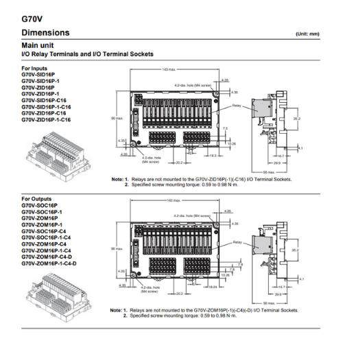
• I/O Relay Terminals with 16 points to mount G2RV Slim I/O Relays.
• Push-In Plus terminal blocks are used to save wiring work in comparison with traditional screw terminals. (Wiring time is reduced by 60%*1 in comparison with traditional screw terminals.)
• Work is reduced ever further with one-step cable connection to the PLC.
• Diode provided for coil surge absorption.
• Operation indicators for immediate recognition of I/O signal status.
• Accepts G3RV Slim I/O SSRs. *2
• Greatly reduce wiring work and maximize space efficiency with new models that provide internal connections between I/O terminals. (input models: 16 point/common, output models: 4 points/common)
• DIN Track or screw mounting.
*1. According to OMRON actual measurement data from November 2015.
*2. Mounting of some models is not possible.
Specifications
Specifications
Coil Ratings (Common to Input/Output per Relay)
| Rated voltage (V) |
Rated current (mA) |
Coil resistance (Ω) |
Must operate of rated voltage |
Must release of rated voltage |
Maximum voltage of rated voltage |
Power consumption (mW) |
|---|---|---|---|---|---|---|
| 24 VDC | 13.3 | 1,575 | 80% max. | 10% min. | 110% | Approx. 280 |
Note:
1. The rated current and coil resistance are measured at a coil temperature of 23°C with a tolerance of ±15% for coil resistance.
2. The operating characteristics are measured at a coil temperature of 23°C.
3. The value for maximum voltage is the maximum value within the allowable voltage fluctuation range for the relay coil’s operating power supply. Continuous operation at this voltage is not within product specifications.
4. The rated current includes the current for the indicators on the I/O Relay Terminal.
Contact Ratings (G2RV-1-S-G I/O Relay)
| Item | For input | For output | |
|---|---|---|---|
| Resistive load (cosφ=1) |
Resistive load (cosφ=1) |
Inductive load (cosφ=0.4 L/R=7 ms) |
|
| Rated load | 50 mA at 30 VAC 50 mA at 36 VDC |
6 A at 250 VAC 6 A at 30 VDC |
2.5 A at 250 VAC 2 A at 30 VDC |
| Rated carry current | 50 mA | 6 A/point, 10 A/common | |
| Max. switching voltage | 30 VAC, 36 VDC | 250 VAC, 125 VDC | |
| Max. switching current | 50 mA | 6 A/point, 10 A/common | |
| Maximum switching capacity | --- | 1,500 VA 180 W |
500 VA 60 W |
| Error rate (reference value) * |
1 mA at 100 mVDC | 10 mA at 5 VDC | |
| Electrical endurance | 5,000,000 operations min. | NO contacts: 70,000 operations min. NC contacts: 50,000 operations min. |
|
| Mechanical endurance | 5,000,000 operations min. | 5,000,000 operations min. | |
* The above values are for a switching frequency of 120 operations/min.
Characteristics
| Item | G70V-SID16P(-1)(-C16) (Input, DC coil) |
G70V-SOC16P(-1)(-C4) (output, DC coil) |
|
|---|---|---|---|
| Contact form | SPST-NO × 16 | SPDT × 16 | |
| Contact material | Ag alloy + Au plating | Ag alloy | |
| Contact resistance *1 | 150 mΩ max. | ||
| Must Operate time *2 | 20 ms max. | ||
| Release time *2 | 40 ms max. | ||
| Max. switching frequency |
Mechanical limit | 18,000 operations/h | |
| At rated load | 1,800 operations/h (under rated load) | ||
| Insulation resistance | 100 MΩ min. | ||
| Dielectric strength | Between coil and contacts: 2,500 VAC for 1 min | ||
| Vibration resistance | 10 to 55 to 10 Hz with 0.5-mm single amplitude (1.0-mm double amplitude) | ||
| Shock resistance | 100 m/s2, 3 times each in 6 directions along 3 axes | ||
| Noise immunity | Noise level: 1.5 kV; pulse width: 100 ns to 1 μs | ||
| Ambient operating temperature |
-40 to 55°C (with no icing or condensation) | ||
| Ambient operating humidity | 35% to 85% | ||
| LED color | Power supply | Green | |
| I/O | Yellow | ||
| Weight | Approx. 350 g | Approx. 370 g | |
Note: The above values are initial values.
*1. Measurement: 1 A at 5 VDC.
*2. Ambient temperature: 23°C.
Approved Standards
The rated values for safety standard certification are not the same as individually defined performance values. Always check the specifications before use.
UL standard certification (File No. E95399)
| Type | Model | Ratings | Standard number |
Category | Listed/ Recognized |
Contact ratings |
|---|---|---|---|---|---|---|
| I/O Relay Terminal |
G70V-SID16P(-1) | 24V DC | UL: 61010-2-201 CSA: C22.2 No.61010-2-201 |
NRAQ, NRAQ7 |
Listed | 24V DC |
| G70V-SID16P(-1)-C16 | ||||||
| G70V-SOC16P(-1) | 250V AC / 30V DC Resistive 4A at 40°C |
|||||
| G70V-SOC16P(-1)-C4 | ||||||
| I/O Terminal Sockets |
G70V-ZID16P(-1) | Recognized | 24V DC | |||
| G70V-ZID16P(-1)-C16 | ||||||
| G70V-ZOM16P(-1) | 250V AC / 30V DC Resistive 4A at 40°C |
|||||
| G70V-ZOM16P(-1)-C4 | ||||||
| G70V-ZOM16P(-1)-C4-D |
Note:
1. USL refers to certification in the US, and CNL refers to certification in Canada.
2. cULus certification has been obtained in Canada. (CAN/CSA-C22.2 No. 61010-2-201)
G70V-SOC16P(-1)(-C16)(-C4), G70V-ZOM16P(-1)(-C16)(-C4)(-D): UL certification specifications
TÜV Rheinland certification (Certification No. R50327604)
| Type | Model | Ratings | Standard number |
Operating coil |
Contact ratings |
|---|---|---|---|---|---|
| I/O Relay Terminal |
G70V-SID16P(-1) | 24V DC | EN 61810-1 | 24V DC | 24V DC 0.05A L/R=0ms |
| G70V-SID16P(-1)-C16 | |||||
| G70V-SOC16P(-1) | single load: 250V AC 6A cos(phi)=1 16 loads: 250V AC 3A cos(phi)=1 16 loads: 30V DC 3A L/R=0ms 16 loads: 250V AC 5A cos(phi)=1 (Ta=+25°C) 16 loads: 30V DC 5A L/R=0ms (Ta=+25°C) |
||||
| G70V-SOC16P(-1)-C4 | 250V AC / 30V DC 16 loads: 5A (Ta=+25°C) 16 loads: 3A (Ta=+55°C) 1 load: 6A Resistive load total max. 10A common line |
||||
| I/O Terminal Sockets |
G70V-ZID16P(-1) | 24V DC | EN 61810-1 | 24V DC | 24V DC 0.05A L/R=0ms |
| G70V-ZID16P(-1)-C16 | |||||
| G70V-ZOM16P(-1) | single load: 250V AC 6A cos(phi)=1 16 loads: 250V AC 3A cos(phi)=1 16 loads: 30V DC 3A L/R=0ms 16 loads: 250V AC 5A cos(phi)=1 (Ta=+25°C) 16 loads: 30V DC 5A L/R=0ms (Ta=+25°C) |
||||
| G70V-ZOM16P(-1)-C4 | 250V AC / 30V DC 16 loads: 5A (Ta=+25°C) 16 loads: 3A (Ta=+55°C) 1 load: 6A Resistive load total max. 10A common line |
||||
| G70V-ZOM16P(-1)-C4-D |
CE Marking Compliance
| Model | EMC Directive | Low Voltage Directive | Machinery Directive |
|---|---|---|---|
| G70V | Not applicable | ❍ | Not applicable |
Note:
1. The Safety Category refers to the maximum applicable category selected when constructing control system safety components. The category does not apply to individual components.
2. Details and other information on conformity levels are issued as part of the "EU Declaration of Conformity." Please contact your OMRON representative for more information.


- D3, Dong Khoi, Group 23, Quarter 35, Tam Hiep Ward, Dong Nai Province, Vietnam
- (+84) 2513 857 563
- info@ngananhphat.com, sales@ngananhphat.com
- www.ngananhphat.com

Giấy phép đăng ký kinh doanh số : 3600955737 do Sở Kế Hoạch & Đầu Tư Tỉnh Đồng Nai cấp ngày 19/11/2007.